 |
|||
|
|
|||
|
|
|||
| ||||||||||
|
|  TM 11-5820-509-35
CHAPTER 5
DEPOT MAINTENANCE
5-3. Equipment Adjustments
5-1. General
The following instructions detail complete module and
a. Instructions are included in this chapter that
subassembly electrical adjustments and calibrating
detail the adjustment, alignment, and bench checkout of
procedures to assure that the receiver transmitter meets
the separate subassemblies of the receiver-transmitter
the performance requirements specified by the original
before re-installation of these modules in the radio set
procurement document.
following overhaul procedures.
Several receiver-
transmitter tests are included in this chapter that cannot
5-4. Transmit Mixer Balance and Transmitter Gain
be performed at lower echelon activities because of the
peculiar test equipment requirements.
Control Adjustment
describe in detail the procedures necessary to isolate
a. Test Equipment and Material.
trouble within the modules and subassemblies of the
(1) Spectrum Analyzer AN/UPM-110
receiver-transmitter.
The general replacement
(2) Converter, Hewlett-Packard K15-8551B
techniques contained in paragraph 3-8 apply equally to
(3) Dummy Load DA-75/U
the depot maintenance level.
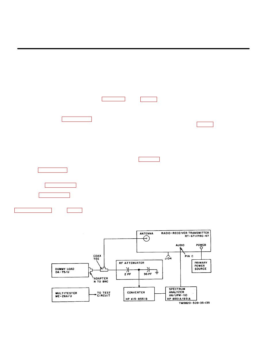
(4) Attenuator (see fig. 5-1)
(5) Multimeter ME-26A/U
(6) Primary power source: 115-volt, 400-Hz,
CAUTION
single-phase, 3 amp.
Remove all power from Radio Receiver-
b. Test Conditions and Equipment Connections.
Transmitter RT-671/PRC-47 before beginning
(1) Connect the test equipment to Radio
any repair procedures.
Receiver-Transmitter RT-671/PRC-47 as shown in
5-2. Replacement of Parts
do so.
a. Parts removal and replacement techniques are
(2) Connect the primary power source to the
described in paragraph 3-9 of this technical manual.
receiver-transmitter.
b. Removal and replacement of the plug-in
(3) Turn on the test equipment and place the
modules and subassemblies of the receiver transmitter
POWER-LIGHTS switch on RT-671/PRC-47 to POWER
are provided in paragraph 3-12.
ON. Permit the equipment to stabilize for at least 5
c. Module disassembly and reassembly techniques
minutes before beginning the procedures listed in the
are listed in paragraph 3-13.
chart below.
d. Mechanical subassemblies are disassembled
and reassembled using the procedures detailed in
instructions are required in connection with these
subassemblies and modules.
Figure 5-1. Transmit Mixer Balance and Transmitter Gain Control Adjustment, Equipment Setup.
5-1
|
|
Privacy Statement - Press Release - Copyright Information. - Contact Us |
