 |
|||
|
|
|||
|
Page Title:
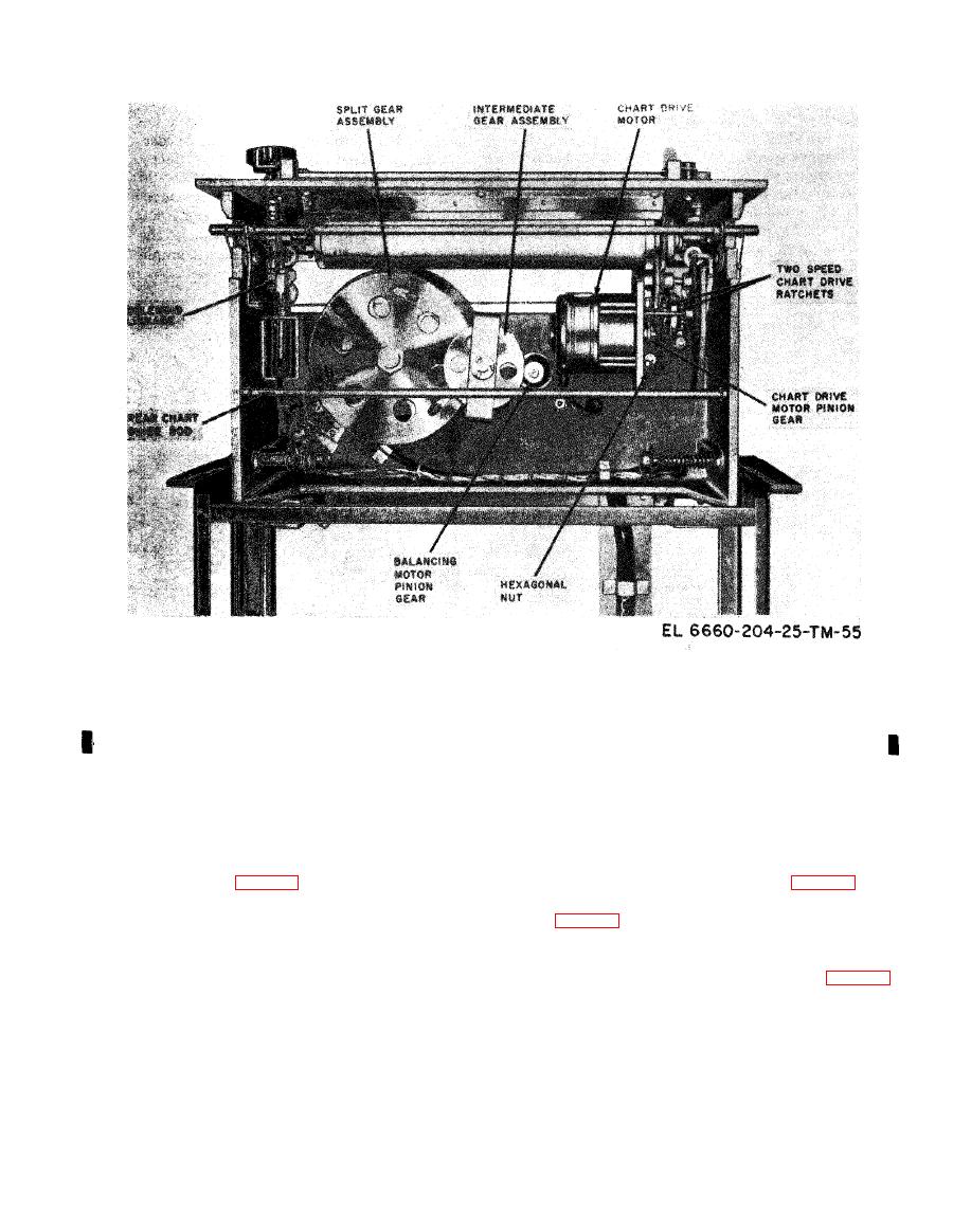
Figure 4-18. Frequency-Time Recorder, Bottom View Showing Main Chart Drive Components. |
|
||
| ||||||||||
|
|  TM 11-6660-204-25
a. Operate the circuit breakers and power switch
Since the types of noise on the received radiosonde
to the ON position.
signals vary with atmospheric conditions and ra-
b. Operate the SIGNAL SELECTOR switch to
d i o s o n d e systems, the noise-suppression diode
S.C. and let the recorder warm up for 15 minutes.
should be aligned only when the radiosonde signals
c. Unlock the control panel and draw the recorder
are being received. An oscilloscope will be required to
forward sufficiently to reach the split gear assembly
align the noise suppression diode properly.
on the bottom side (fig. 4-18). Apply finger pressure
the signal is not noisy, set noise suppression switch
to the rim of the split gears and force the pen slightly
S301 (fig. 3-15 to the OUT position. If the signal is
to the right; then remove the force slowly, so that the
noisy, set noise suppression switch S301 to the IN
pen carriage will not jump back into its former posi-
tion. Let the pen record in its percent position for 10
position.
or 15 seconds. Next, force the pen a little to the left.
3-15) to their maximum clockwise position.
Release slowly, and again allow a short chart record-
ing. If there is any difference between the two record-
ground.
ings (hysteresis error), this difference should be cen-
d. If noise appears on the oscilloscope at jack
tered on the chart zero line by adjusting the REC.
J307, adjust potentiometers R304 and R306 as fol-
lows:
|
|
Privacy Statement - Press Release - Copyright Information. - Contact Us |
