 |
|||
|
|
|||
|
Page Title:
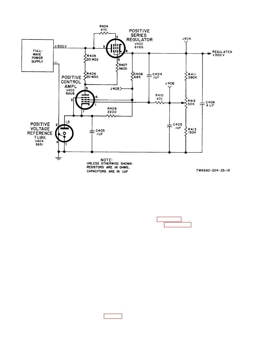
Figure 2-17. Positive regulated power supply, simplified schematic diagram. |
|
||
| ||||||||||
|
|  TM 11-6660-204-25
gardless of normal variations in the input voltage
(4) A 6.3-volt winding with one side of the
or load conditions,
filament connected to circuit ground (terminals
(1) Rectifier tube V401 functions as a con-
15, 16, and 17) supplies voltage to the pen heater,
ventional full-wave rectifier. This circuit is shown
panel lamps, and to each of the filaments of tubes
V303, V310, V405, V406, V409, and V410.
as a block in figure 217; for individual compo-
nents, refer to figure FO-6. Fuses F401 and F402
(5) A 6.3-volt winding with a center tap
are connected in series with the plate leads of
(terminals 18, 19, and 20 of the transformer)
rectifier tub V401 for overload protection. Capac-
supplies filament voltage for tubes V301, V302,
itor C401 and C402, with choke coil L401, com-
and V403. The center tap is connected to a posi-
prise a one-section pi filter for the unregulated
tive 80-volt tap on the 300-volt supply so the fila-
power supply. Bleeder resistor R401 discharges
ments of these tubes will be near the potential of
the filter capacitors when the equipment is turned
their cathodes to reduce the possibility of fila-
off. The center tap of the plate winding is re-
ment-cathode arc-over.
turned to circuit ground. The filtered but unregu-
(6) A 6.3-volt winding with a center tap
lated 500 volts is connected to the plate of series
(terminals 21,22, and 23 of the transformer) sup-
reglator tube V402. The screen-grid voltage is
plies filament voltage for tube V402. The center
obtained from the unregulated supply through
tap is connected to the positive 300-volt supply so
screen-grid voltage dropping resistor R404. Resis-
the filaments of tube V402 will be near the poten-
tor R407 is a grid-current limiting resistor. The
tial of its cathode to reduce the possibilitv of fila-
300-volt regulated output is taken from the cath-
ment-cathode arc-over.
ode of tube V402. A voltage divider, which ad-
j usts the output voltage consisting of resistors
R411 and R413 with potentiometer R412, is
2-17) furnishes a constant positive 300-volts re-
placed across the positive 300 volts and circuit
|
|
Privacy Statement - Press Release - Copyright Information. - Contact Us |
