 |
|||
|
|
|||
|
Page Title:
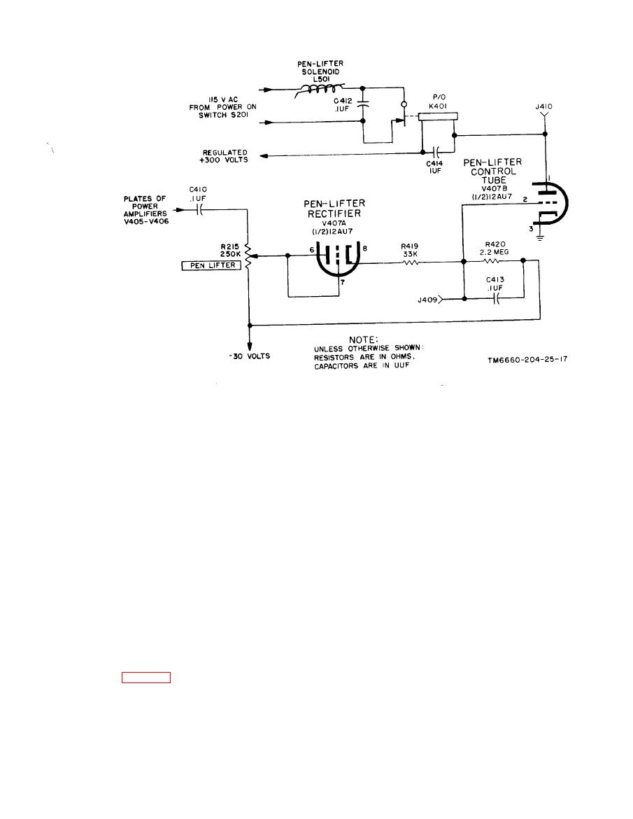
Figure 216. Pen-lifter circuit, simplified schematic diagram. |
|
||
| ||||||||||
|
|  TM
11-6660-204-25
c. Pen-lifter solenoid L501, when not energized,
ating voltages for the circuits in the radiosonde
recorder.
is actuated by a spring to hold the recorder pen
off the chart. When energized, through the nor-
mally closed contacts of relay K401, it keeps the
ate from 105 to 125 volts at 50 to 65 CPS, with
recorder pen against the chart. When a signal is
the capability of applying the following voltages
received, the dc voltage developed across resistor
from its secondaries:
R420 overcomes the --30-volt bias. Tube V407B
(1) A voltage of 435 volts on each side of the
then conducts and operates relay K401 which, in
center tap (terminals 3, 5, and 7) to supply the
turn, removes the 115 volts ac from pen-lifting
plate voltage to positive supply rectifier tube
solenoid L501. This permits the spring to pull the
V401. Also 115 volts center tapped (terminals 4,
recorder pen to its up position, so the recorder
5, and 6 of that same secondary) are used to sup-
chart is not marked while the balancing motor is
ply excitation to the vibrator inverter coil through
moving the slide-wire to its balance point. When
capacitor C317. Terminal 6 also supplies a 57-volt
switch S201 on the control panel is in the STAND
test signal for S202 on the control panel.
BY position, 115 volts ac is removed from the pen
solenoid, and the pen rests in its up position until
(3) A voltage of 320 volts on each side of the
center tap of the transformer terminals 8, 9, and
the switch is returned to POWER ON.
10 supply the plate voltage to negative supply rec-
tifier tube V408.
2-17. Power Supply
(3) Two 5-volt windings (terminals 11 and
12; 13 and 14) form the filaments of positive sup-
ply V401 and negative supply V408 rectifier tubes,
The power supply consists of one positive regu-
lated supply, one negative regulated supply, and
respectively. Terminal 13 of the transformer also
has the unfiltered ripple voltage of the 175-volt
one unregulated supply, obtained from a single
negative supply which is applied direct to the 120
power transformer. The power supply furnishes
CPS terminal of switch S202 on the control panel.
filament voltages for all the tubes and all de oper-
|
|
Privacy Statement - Press Release - Copyright Information. - Contact Us |
