 |
|||
|
|
|||
|
Page Title:
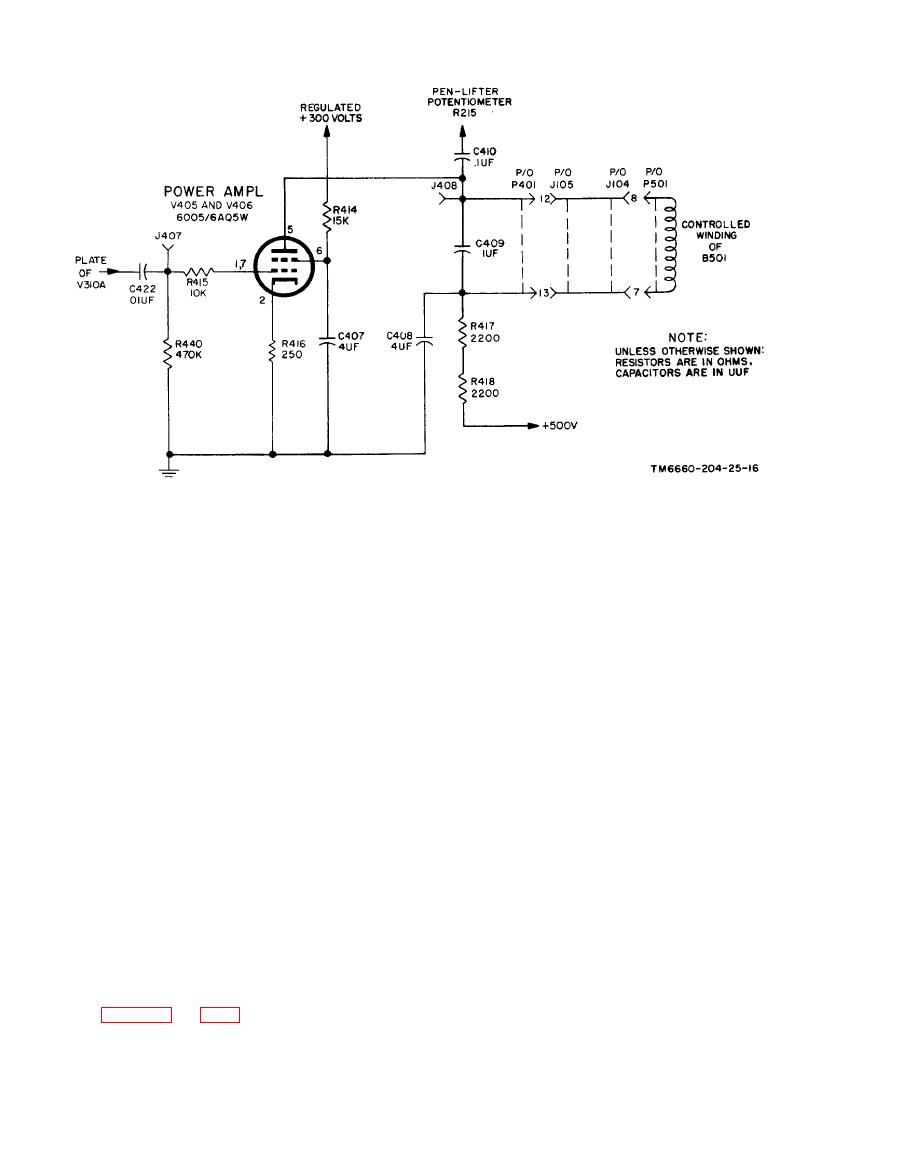
Figure 2-15. Power amplifier, simplified schematic diagram. |
|
||
| ||||||||||
|
|  TM 11-6660-204-25
a rectifier and the other half ( V407B ) functions
through dropping resistor R414. The screen-grid
as an amplifier control. In operation when a signal
is bypassed to circuit ground by capacitor C407.
is received from the power amplifiers, the pen
Cathode bias is produced by the voltage drop
rises from the chart when it travels to its new
across cathode resistor R416, which is unbypassed
position. The solenoid, however, does not lift the
for degenerative purposes.
pen but merely releases a spring that performs
c. The ac error signal is applied from the plate
the lifting. An energized solenoid compresses the
of tube V310B, through coupling capacitor C422,
spring and allows the pen to lower.
across grid resistor R440, to the control grids of
b. The amplified ac error signal from the plates
tubes V405 and V406 and through grid-current
of tubes V405 and V406 is fed through coupling
limiting resistor R415. The output power is ap-
capacitor C410 to pen-lifter potentiometer R215.
plied to the control winding of balancing motor
A portion of this ac error voltage, determined by
B501 and C409 which is a parallel-tuned circuit.
the position of the PEN LIFTER potentiometer
arm, is rectified by tube V407A and dc voltage is
d. When a signal is applied to the grid of tubes
developed across resistors R419 and R420. The
V405 and V406, an amplified drop with the proper
voltage developed across resistor R420 and fil-
phase is developed across the tuned circuit of the
tered by capacitor C403 is applied to the grid of
motor winding (B501) to drive the motor. A por-
control tube V407B. The entire rectifier circuit is
tion of this plate signal voltage is also applied,
returned to a negative 30-volt bias supply which
through capacitor C410, to pen-lifter potentiome-
is obtained from the junction of bleeder resistors
ter R215 to operate the pen-lifter circuit. Jacks
R436 and R437, across the negative regulated 175-
J407 and J309 can be used for checking grid and
volt supply. The negative 30-volt bias holds pen-
plate voltages.
lifter control tube V407B at cutoff during no-sig-
nal conditions. Potentiometer R215 is used to ad-
2-16. Pen-Lifter Circuit
just pen-lifter operation for various noise levels
and is set low so the internal noise of the ampli-
fier circuit does not overcome the fixed bias of
a. The pen-lifter circuit uses both sections of
tube V407B, but is set sufficiently high to obtain
miniature twin-triode tube V407. One half of the
reliable operation for input signals.
tube (V407A) is connected as a diode and used as
|
|
Privacy Statement - Press Release - Copyright Information. - Contact Us |
