 |
|||
|
|
|||
|
Page Title:
Chapter 6. GS AND DEPOT MAINTENANCE |
|
||
| ||||||||||
|
|  TM 11-6625-924-14
CHAPTER 6
GS AND DEPOT MAINTENANCE
Section I. TROUBLESHOOTING
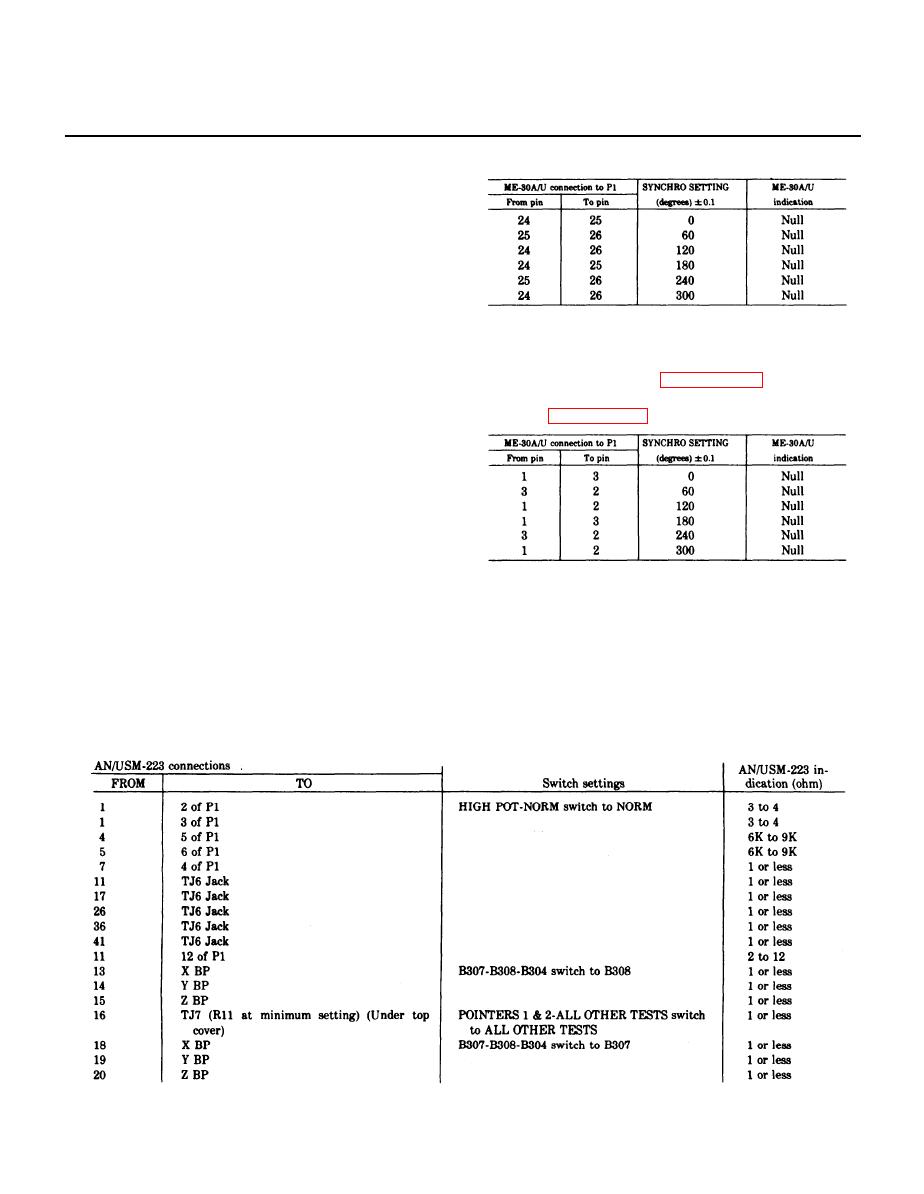
6 - 1 . General
Troubleshooting the test panel consists of performing
voltage tests on the synchro transmitters and resis-
tance measurements on the entire test panel. Measure-
ments are made through pins of the test cable connec-
tor or binding posts. If an erroneous indication is ob-
.
served, check the circuit connected to the pin or bind-
6-4. Synchro Transmitter No. 2 Test
ing post at which the erroneous indication was ob-
a. Connect a jumper between pins 2 and 11 of con-
served.
nector P1.
6 - 2 . Test and Additional Equipment Re-
quired
except, use the following chart instead of the one refer-
red to in paragraph 6-3d.
a. Multimeter AN/USM-223.
b. Voltmeter, Meter ME-30A/U.
c. 115 VAC, 400-Hertz power supply.
6-3. Synchro Transmitter No. 1 Test
a. Connect alligator clips on the power cable to the
115 VAC, 400-Hertz power source.
b. Set the ADF-VOR-RMI switch to the VOR posi-
tion.
C. Set the ON-OFF switch to the ON position.
Perform the resistance measurements in the chart
d. Perform the test in the chart below by connecting
below by connecting the AN/USM-223 between the
the ME-30A/U between the pins of connector P1 indi-
pins of connector Pl, binding posts (BP), or test jacks
(TJ) under top cover indicated in column 1, setting
cated in column 1, setting the synchro transmitter No.
switches in column 2 (if indicated), and obtaining the
1 control as indicated in column 2, and obtaining the
readings in column 3.
ME-30A/U indication in column 3. The synchro
NOTE
transmitter No. 1 dial should indicate within 0.1
Switch settings for any measurement are as
previously indicated unless otherwise stated.
degree in each position.
6-1
|
|
Privacy Statement - Press Release - Copyright Information. - Contact Us |
