 |
|||
|
|
|||
|
Page Title:
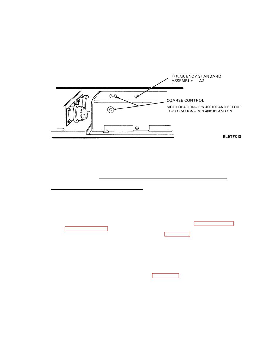
Figure 5-1. Frequency Standard Crystal Oscillator Adjustment. |
|
||
| ||||||||||
|
|  TM 11-5820-918-13
Frequency Standard Crystal Oscillator Adjustment.
PERFORMANCE
TEST
PROCEDURES
expedient method of checking overall transmitter operation within the limits for field
maintenance. The order of performing the tests will depend entirely on the anticipated
status of the equipment. If the equipment is suspected of being below specifications,
then the complete test in the order presented should be performed. If the equipment
is being tested only for an over-all check, the RF power test (paragraph 5-22) and fre-
quency test (paragraph 5-23) should be performed first and any others as appropriate.
The test equipment needed for the tests is listed in table 5-1.
amplifier (5018), and the filter set and filter decode (4011).
Switch the TCS-4B transmitter off, and disconnect the antenna from the 4011
(J7).
b. Set up the test equipment as shown in figure 5-2. The RF wattmeter is con-
netted to the 4011 RF out connector (J7) on the front panel.
c. On the 1024, the DIRECT/DIPLEX switch is placed in DIRECT , and the power
output .1 PWR/FULL PWR switch is placed in FULL position, and the sweep limit set
for 2-30 MHz.
d.
Set the RF wattmeter to the 150 watt scale.
|
|
Privacy Statement - Press Release - Copyright Information. - Contact Us |
