 |
|||
|
|
|||
|
Page Title:
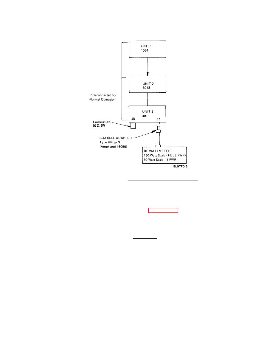
Figure 5-2. Power Amplifier Test Setup. |
|
||
| ||||||||||
|
|  TM 11-5820-918-13
Power Amplifier Test Setup.
This test checks the frequency sweep of the transmitter.
a.
Switch the TCS-4B transmitter off and disconnect the antenna.
b.
Set up the test equipment as shown in figure 5-4.
c. On the 1024, place DIRECT/DIPLEX switch in DIPLEX position and the power
output .1 PWR/FULL PWR switch in .1 PWR position, and the sweep limits to 2-30 MHz.
CAUTION
This test must be performed with the DIRECT/DIPLEX switch in the DIPLEX
position and the .lPWR/FULL PWR switch in the .1 PWR position. If these
switch settings are not observed, severe damage to test equipment could
occur.
d. Set the frequency counter to read frequencies from 2 to 30 MHz.
Turn on TCS-4B transmitter.
e.
f. With the 1024 MODE switch in MAN position, press RESET, then press START.
Before the 1024 frequency MHz display reaches 3.00, press STOP. Compare the 1024
frequency reading with the reading on the frequency counter. The readings should
be equal.
|
|
Privacy Statement - Press Release - Copyright Information. - Contact Us |
