 |
|||
|
|
|||
|
Page Title:
Replacement of Parts in Power Supply Chassis Assembly 2A1A5 |
|
||
| ||||||||||
|
| 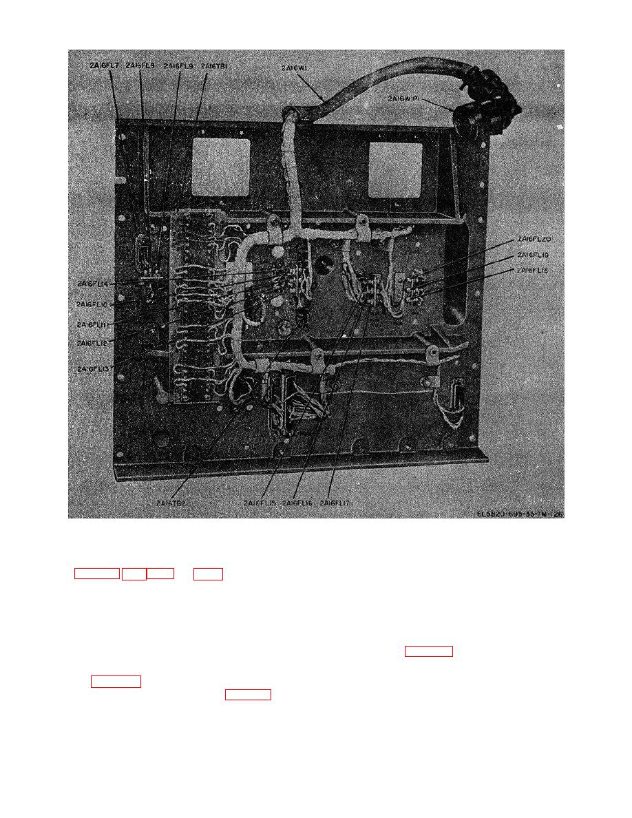 TM 11-5820-695-35
Figure 3-21. Plate assembly 2A16, rear view, parts location.
3-40.
Replacement of Parts in Power Supply
(1) Set the POWER ON/OFF switch on meter
Chassis Assembly 2A1A5
panel assembly 2A15A2 to OFF.
(2) Loosen the two meter panel captive
screws on meter panel assembly 2A15A2 (.fig. 3817).
To replace any part in power supply chassis assembly
(3) Position meter panel assembly upward
2A1A5, remove power supply 2A1 (a below) and refer to
and lock it in position by use of the panel looking latch
applicable replacement procedure (b through f below)
(fig. 8-19).
for the part to be replaced. After the part has been
(4) Alternately unscrew each power supply
replaced, refer to the steps in g below for replacement
captive screw (fig. 3-17) one or two turns at a time.
of power supply 2A1. Parts located on terminal board
Repeat this procedure until both captive screws rotate
2AlA5TB1 are removed using standard soldering
freely.
techniques (para 3-19).
3-63
|
|
Privacy Statement - Press Release - Copyright Information. - Contact Us |
