 |
|||
|
|
|||
|
Page Title:
Receiver, Radio R-1467(P)/GRC-144(V) DC Power Distribution |
|
||
| ||||||||||
|
|  TM 11-5820-695-35
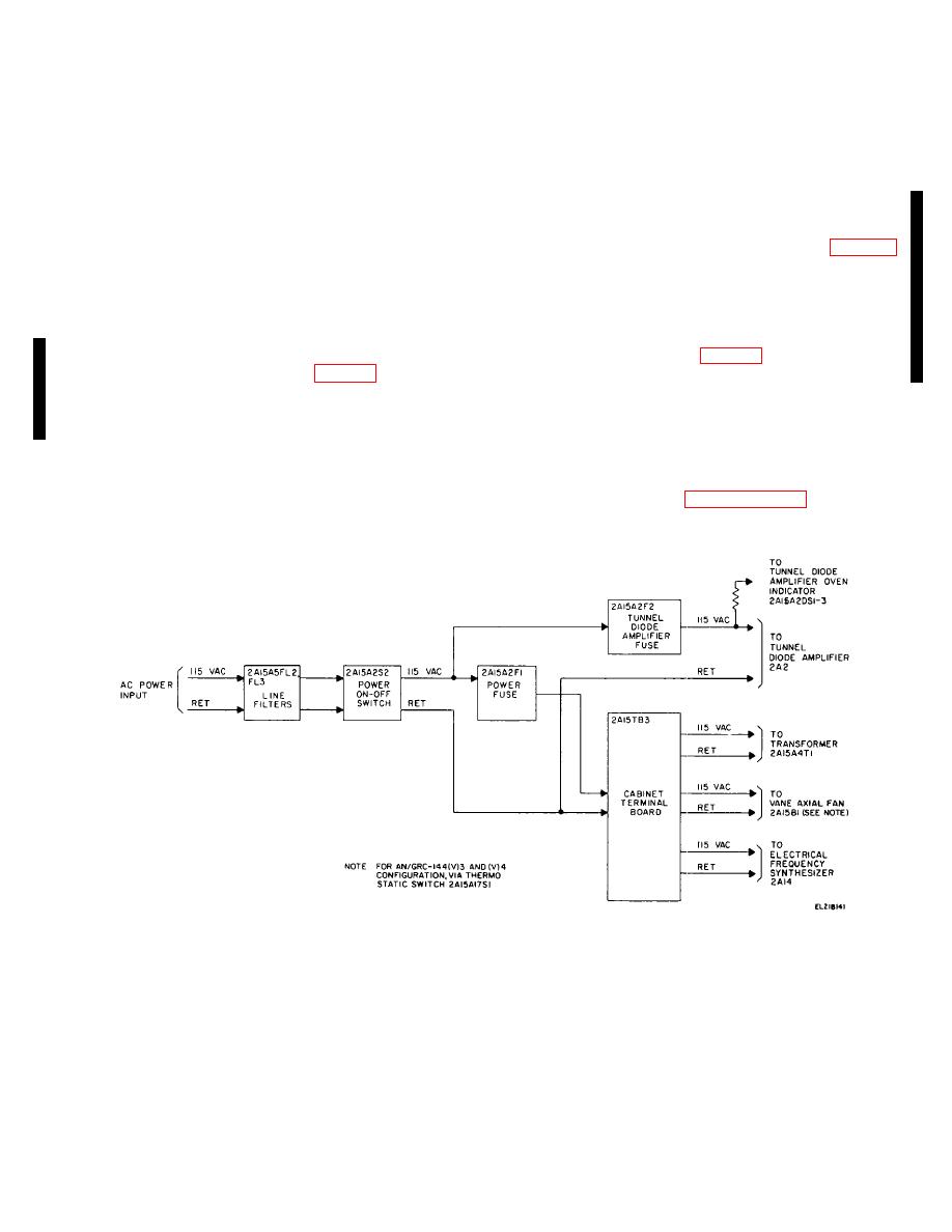
terminal board 2A15TB3 and through the tunnel diode
CARR IF indication informs the operator that the 70
amplifier fuse (2A15A2F2) to tunnel diode amplifier 2A2
MHz if carrier is at a low level or is not present. Also,
and to tunnel diode oven amplifier Indicator
for this condition, the receiver summary alarm circuit is
2A15A2DS13. Terminal board 2A15TB3 distributes 115
activated.
vac primary power to power transformer 2A15A4T1,
vane axial fan 2A15B1, and electrical frequency
(4) The summary alarm circuit is comprised
synthesizer 2A14. Refer to the Receiver, Radio R-
of diode OR gate CR12, CR15 and CR16 and transistor
1467(P)/GRC-144(V) interconnecting diagram (fig. 5-21)
Q23. Each of the normal outputs is connected to the
for point-to-point primary power connections. For the
OR gate. For normal operation, transistor Q23 is off
AN/GFC-144(V) 3 and 4 configurations, 115 vac passes
(nonconducting). When any one of the alarm conditions
to fan 2A1581 through thermostatic switch 1A15A17S1.
occur, the OR gate switches Q23 turn on (conducting
state) causing a receiver summary alarm condition.
2-26.
Receiver, Radio R-1467(P)/GRC-144(V) DC
2-25.
Receiver,
Radio
R-1467(P)/GRC-144(V)
Power Distribution (fig. 2-8)
Primary Power Distribution (fig. 2-7)
The 115 vac input from 2A15TB3 is applied to power
transformer 2A15A4T1 where it is transformed into four
The 115 vac primary power is applied to Receiver,
ac outputs: 29 vac (w), 19 vac (x), 18 vac (y), and 30
Radio R-1467(P)/GRC-144(V) through AC POWER
vac (z). Each output is applied to a voltage regulator in
INPUT connector 2A15A5J5. The 115 vac input passes
power supply 2A1. Three 15/28v voltage regulators and
through line filters 2A15A5FL2 and FL3 to POWER ON-
one 12v voltage regulator are utilized. A typical voltage
OFF switch 2A15-A2S2 on meter panel assembly
regulator is described in paragraph 2-18. The voltage
2A15A2. When the POWER ON-OFF switch is set to
regulators provide four regulated dc voltage outputs:
ON, 115 vac passes through the fuse 2A15A2F1 to
Figure 2-7. Receiver, Radio R-1467(P)/GRC-144(V) and R-1467(P) A/GRC-144(V),
Primary Power Distribution
Change 6
2-52
|
|
Privacy Statement - Press Release - Copyright Information. - Contact Us |
