 |
|||
|
|
|||
|
Page Title:
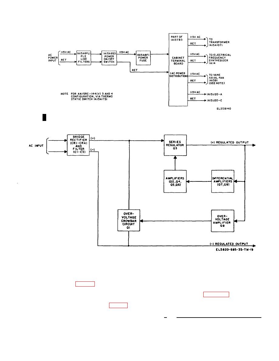
Figure 2-6. Typical voltage regulator 1A1A1-1A1A12, block diagram. |
|
||
| ||||||||||
|
|  TM 11-5820-695-35
Figure 2-5. Transmitter, Radio T-1054(P)/GRC-144(V) and T-1054(P)A/GRC-144(V),
primary power distribution block diagram.
Figure 2-6. Typical voltage regulator 1A1A1-1A1A12, block diagram.
interconnecting diagram (fig. 5-15), and power supply
regulators. The voltage regulators consist of a bridge
1A1 interconnecting diagram (fig. 5-17), for point-to-
rectifier and filter, series regulator, and overvoltage
point dc voltage connections.
protection circuits. The description is based on the
block diagram shown in figure 2-6. Circuit theory
descriptions for each regulator are given in paragraph 2-
2-18.
Typical Voltage Regulator 1A1A1 Through
28.
1A1A12 Block Diagram Description (fig. 2-6)
a.
Bridge Rectifier and Regulator Circuit.
Since the 5/6v, 12v, and 15/28v voltage regulators are
The output of bridge rectifier CR1 through CR4 is
similar, the following description of a 15/28v voltage
regulator covers, in general, the operation of all three
Change 6
2-44.1/(2-44.2 blank)
|
|
Privacy Statement - Press Release - Copyright Information. - Contact Us |
