 |
|||
|
|
|||
|
Page Title:
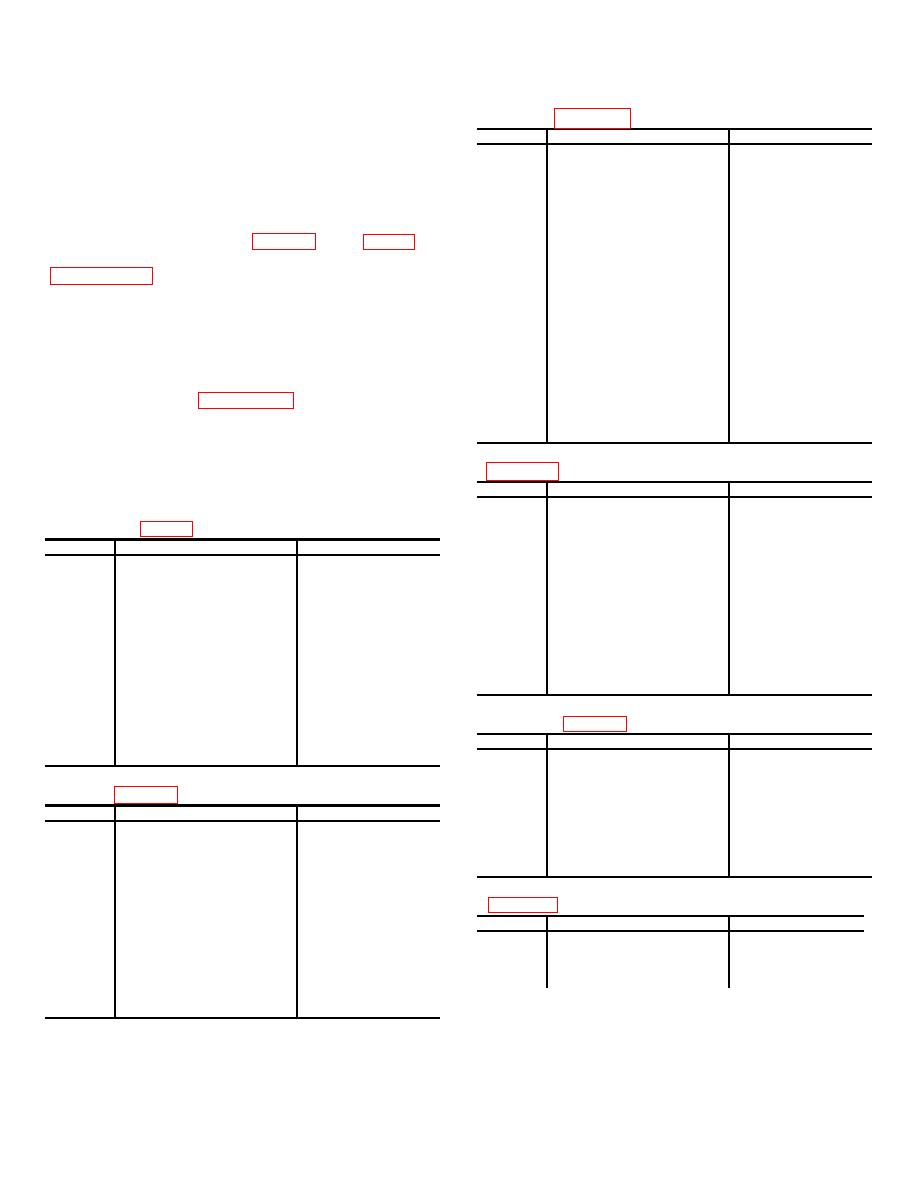
Dc Resistance of Coils and Transformer Windings |
|
||
| ||||||||||
|
|  TM 11-5820-509-35
come in contact with one another or
(3) Signal Data Translator CV-1377A/PRC-
with
the
module
chassis.
47/A8A3 ) (fig. 7-11 ).
Component damage can result.
Ref des
Terminal no.
Resistance (ohms)
A3K1
3 to 4
1,000 10%
c. If abnormal voltage readings are obtained,
A3L1
1 to 2
Less than 1 ohm
remove all power from the module being tested and
to
conduct dc resistance measurements throughout the
A3L81
suspected circuit or stage to isolate any open- or short-
A3L98A
1 to 2
Less than 0.02 ohms
circuit conditions, or defective parts. Refer to the
A3L98B
3 to 4
Less than 0.02 ohms
A3L100
1 to 2
11.1 10%
A3L101
1 to 2
7.5 10%
to the transformer and coil resistance data shown in
A3L102
1 to 2
2 10%
A3L103
1 to 2
Less than 0.02 ohms
A3L120
1 to 2
11.6 10%
d. Trouble that does not completely disable the
A3L121
1 to 2
10 10%
equipments, but which results in decreased receiver
A3L125
1 to 2
Less than 1 ohm
sensitivity or transmitter power output can be difficult to
to
isolate and may become time-consuming. When such
A3L134
A3L135
1 to 2
1.65 10%
symptoms are evident, and all circuit checks fail to
A3L136
1 to 2
Less than 1 ohm
indicate a defective part, check the alignment of the
to
receiver-transmitter /chapter 4) or consult the
A3L145
adjustment routines of section VI.
A3T1
A to B
Less than 0.1 ohm
3-7.
Dc Resistance of Coils and Transformer
(4) Power Supply PP-3518/PRC-47 (A8A5)
Windings
windings is shown in the following charts.
Ref des
Terminal no.
Resistance(ohms)
A5K1
1 to 2
300 10%
(1) Audio Frequency Amplifier AM-3606/PPC-
A5L1
1 to 2
3 10%
47 (A8A1 ) ( fig. 7-9 ).
A5T1
1 to 2
.2 10%
Ref des
Terminal no.
Resistance (ohms)
A5T1
2 to 3
.2 10%
A5T1
3 to 4
.2 10%
A1K1
1 to 2
800 20%
A5T1
4 to 5
.3 10%
A1L1
1 to 2
180 10%
A5T1
6 to 7
13 10%
A1L2
1 to 2
30 10%
A5T1
8 to 9
18.2 10%
A1L2
2 to 3
420 10%
A5T1
10 to 11
65 10%
A1L3
1 to 2
420 10%
A5T1
12 to 13
.3 10%
A1TI
Yellow to green
190 25%
A5T1
13 to 14
.2 10%
A1TI
Red to blue (R12 connected)
780 25%
A5T1
15 to 16
55 10%
A1T2
1 to 2
150 10%
A5T2
1 to 2
12.2 10%
A1T2
3 to 4
15 10%
A5T2
3 to 4
.7 10%
A1T3
1 to 2
325 10%
A1T3
3 to 4
100 10%
(5) Radio Frequency Oscillator 0-1032/PRC-
A1T3
4 to 5
100 10%
47 (A8A6) (fig. 7-13).
A1T5
1 to 2
80 10%
Ref des
Terminal no
Resistance (ohms)
A1T5
2 to 3
80 10%
A6L1
1 to 2
2.6 10%
A1T5
4 to5
100 10%
A6L2
1 to 2
11.6 10%
(2) Amplifier-Modulator
AM-3507/PRC-47
A6L3
1 to 2
7.5 10%
(A8A2)) (fig. 7-10).
A6L4
1 to 2
16.5 10%
A6L5
1 to 2
3.9 10%
Ref des
Terminal no.
Resistance (ohms)
A6L6
1 to 2
72 10%
A2L1
1 to 2
50 10%
A6L7
1 to 2
29 10%
A2L2
1 to 2
16.5 10%
A6L8
1 to 2
21 10%
A2L3
1 to 2
50 10%
A6L9
1 to 2
72 10%
A2L4
1 to 2
4 10%
A2L5
1 to 2
29 10%
(6) Oscillator Control C-4311/PRC-47 (A8A7)
A2L6
1 to 2
3 10%
A2L7
1 to 2
3.5 10%
Ref des
Terminal no
Resistance (ohms)
A2L8
1 to 2
29 10%
A7L1
1 to 2
4.5 10%
A2L9
1 to 2
72 10 %
A7L2
1 to 2
2.6 10%
A2L10
1 to 2
50 10 %
A7L3
1 to 2
50 10%
A2T2
1 to 3
1 10 %
A7L4
1 to 2
11.6 10%
A2T2
4 to 6
0.5 10 %
A2T3
1 to 3
5 10 %
A2T3
4 to 6
1 5 10 %
3-88
|
|
Privacy Statement - Press Release - Copyright Information. - Contact Us |
