 |
|||
|
|
|||
|
|
|||
| ||||||||||
|
| 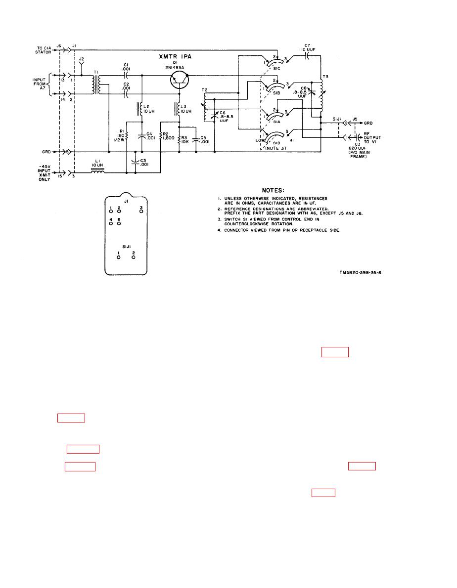 consists of transformer T1, trimmer ca-
the -45-volt supply. A pi-type filter con-
pacitor C1, and inductor L1. When S1 is in
sisting of capacitors C2 and C5 and induc-
the high-band position, the tuned circuit
tor L2 prevents rf variations on the fila-
consists of transformer T2, trimmer ca-
ment of tube V2 and rf leakage into the
pacitor C1, and inductor L1. When S1 is in
2.5-volt filament supply. The combination
C5. Tuning capacitor C2B (fig. 88) is con-
of plate inductor L3 and bypass capacitor
nected in parallel with either T1 or T2
C4 prevents rf leakage into the +125-volt
through S1C.
power supply. Resistor R3 is a screen-
b. During transmission, the output from
grid voltage dropping resistor; capacitor
transmitter power amplifier tube V1 is
C3 is the screen-grid bypass capacitor.
applied from J7 through S1AJ1, contact 2
and contact 1 or 3 of S1A to the selected
tuned circuits (a above). The output signal
from the tuned circuit is applied through
contact 1 or 3 and contact 2 of S1D,
Power amplifier tank module A2 is used
through terminal 1 of 2AJ1 and terminal
as both the output load for power amplifier
11 of J7 to the antenna. Input to the re-
tube V1 (para 19) (in A29), and as the input
ceiver through S1B is prevented by the
circuit for receiver first rf amplifier mod-
energized contacts of relay K1 (fig. 88).
ule A3 (para 6). Module A2 consists of a
During reception, signals from the antenna
low- and a high-band tuned circuit, and a
are passed through S1D to the selected
BAND switch.
tuned circuit. Relay K1 (fig. 88) is not en-
a. BAND switch S1 selects one of two
ergized. During reception, energy from
frequency bands. When S1 is in the low-
the tuned circuit is coupled by inductor
band position (30-52), the tuned circuit
|
|
Privacy Statement - Press Release - Copyright Information. - Contact Us |
