
TB 9-2320-387-35-7
Section VI. INTERFACE PLATE INSTALLATION
NOTE
Perform either BFT installation or EPLRS installation. For BFT
installation, see section V.
Vehicles with serial numbers 235719 and below do not have
interface plates. Vehicles with serial numbers 235720 and above
will have holes drilled and inserts installed.
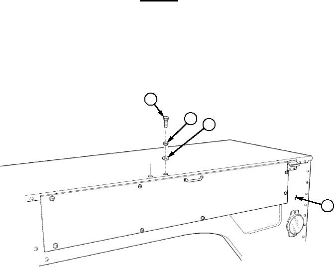
6-1. Remove two capscrews (1), lockwashers (2), and washers (3) from left side wheelhouse (4).
6-2. Place interface plate (5) on left side wheelhouse (4).
6-3. Install two existing capscrews (1), lockwashers (2), and washers (3) in bracket assembly (10). Do not
tighten capscrews (1) at this time.
6-4. Align inboard curved edge of interface plate (5) with inner edge of wheelhouse (4) and ensure
interface plate (5) is positioned correctly.
6-5. Tighten two capscrews (1) to 6 lb-ft. (8 Nm).
6-6. Using interface plate (5) as template, locate, and mark eight hole positions (7) in wheelhouse (4).
6-7. Remove two capscrews (1), lockwashers (2), and washers (3) from wheelhouse (4) and
bracket assembly (10). Discard lockwashers (2).
6-8. Remove interface plate (5) from wheelhouse (4).
CAUTION
Use drill stop to prevent damage to A/C condenser.
6-9. Drill eight 0.391-in. diameter holes (7) in wheelhouse (4).
6-10. Install four inserts (6) in holes marked A and four inserts (8) in holes marked B in left side
wheelhouse (4).
6-11. Install interface plate (5) on left side wheelhouse (4) with two existing capscrews (1),
lockwashers (2), and washers (3). Do not tighten capscrews (1) at this time.
6-12. Secure interface plate (5) to left side wheelhouse (4) with eight screws (9).
6-13. Tighten capscrews (1) and screws (9) to 6 lb-ft. (8 Nm).
1
2
3
4
Figure 5-47.