
TB 9-2320-387-35-7
NOTE
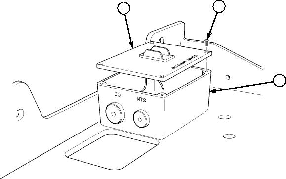
Equipment not shown for clarity.
5-12. Remove screws (26) from lid (25) of antenna switch box (27).
5-13. Route Data/Power with terminal ends (29) of transceiver cable (2) between radio rack (21) and
engine cover (32) through radio rack access hole (28).
5-14. Insert Data/Power with terminal ends (29) of transceiver cable (2) into antenna switch box (27).
5-15. Route Data leg with connector end (35) of transceiver cable (2) between radio rack (21) and engine
cover (32) through rear radio rack access hole (28).
5-16. Connect Data leg connector (35) of transceiver cable (2) to J3 connector (34) of SIAD (33).
5-17. Insert power cable with terminal ends (31) into antenna switch box (27).
5-18. Route power cable (31) through radio rack access hole (28) and to tunnel insulation (30).
5-19. Remove nut (37) and washer (38) from stud (41) in antenna switch box (27).
5-20. Connect negative lead (39) of Data/Power with terminal ends (29) of transceiver cable (2)
to stud (41) in antenna switch box (27).
5-21. Secure negative leads (39) and (40) to stud (41) with existing washer (38) and nut (37).
5-22. Connect negative lead (40) of power cable (31) to stud (41) in antenna switch box (27).
5-23. Install positive lead (44) of Data/Power with terminal ends (29) of transceiver cable (2) to antenna
switch (36) with existing screw (45).
5-24. Install positive lead (43) of power cable (31) to antenna switch (36) with existing screw (42).
5-25. Install lid (25) on antenna switch box (27) with screws (26).
26
25
27
Figure 5-44.
5-40