 |
|||
|
|
|||
|
Page Title:
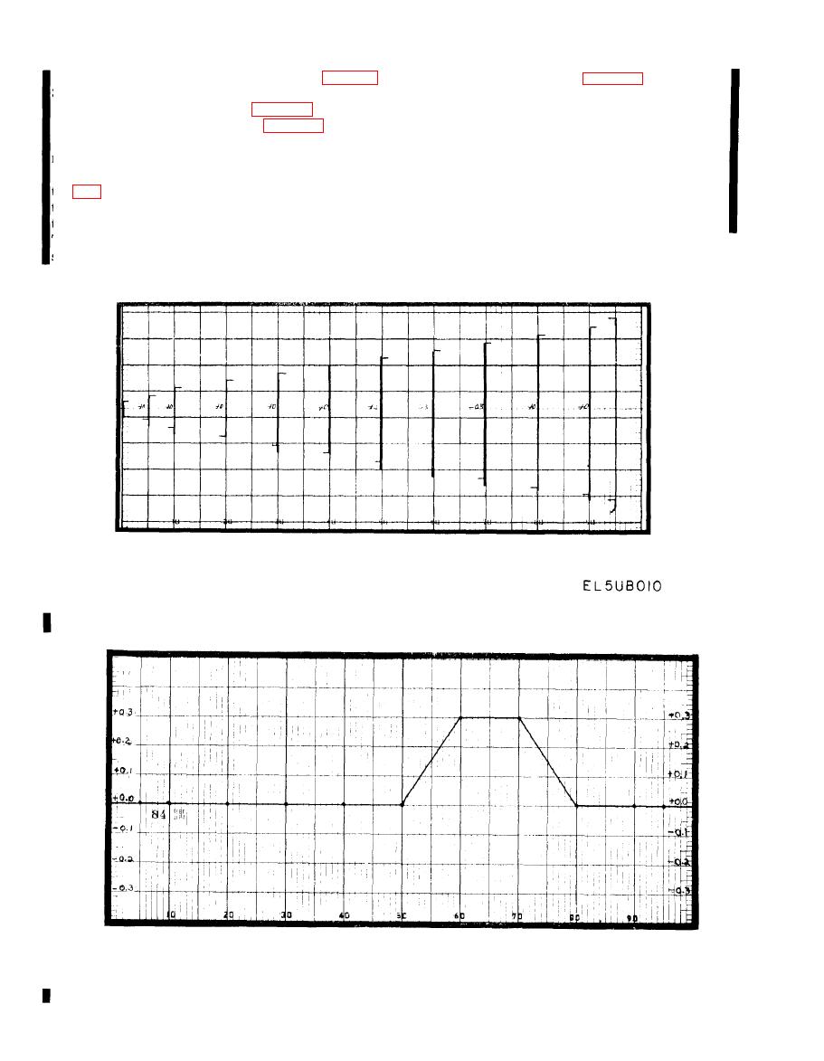
Figure 3-16. Linearity Calibration Test Chart, |
|
||
| ||||||||||
|
|  TM 11-6660-204-25
(2) Loose drive cable (tension adjustment) (para
(7) Incorrect tube types (para 3-24f).
(8) Insufficient warmup time. Normally, 10 min
3-26).
utes is sufficient. Occasionally, a longer warm up
(3) Incorrect split-gear bias(para 3-27).
time is required depending on the ambient tempera
(4) Worn slide-wire contactor (para 3-28c).
ture.
(5) Maladjusted electrical or mechanical adjust-
(9) Tube conductance not balanced. The conduc-
ments.
tance of V304, V305, V306, and V307 should be as
(6) Excessive tension setting on balancing mo-
equally matched as possible. Check tube on a tube
tor (fig. 4 16). Tension is adjusted by the means of
tester and replace any tube indicating a large varia-
the large screw at the top of the motor. Excessive
tion from the other tube conductance.
tension may cause the recorded to respond slowly.
Too little tension will cause the recorder pen to over-
shoot the desired position.
Change 3
|
|
Privacy Statement - Press Release - Copyright Information. - Contact Us |
