 |
|||
|
|
|||
|
Page Title:
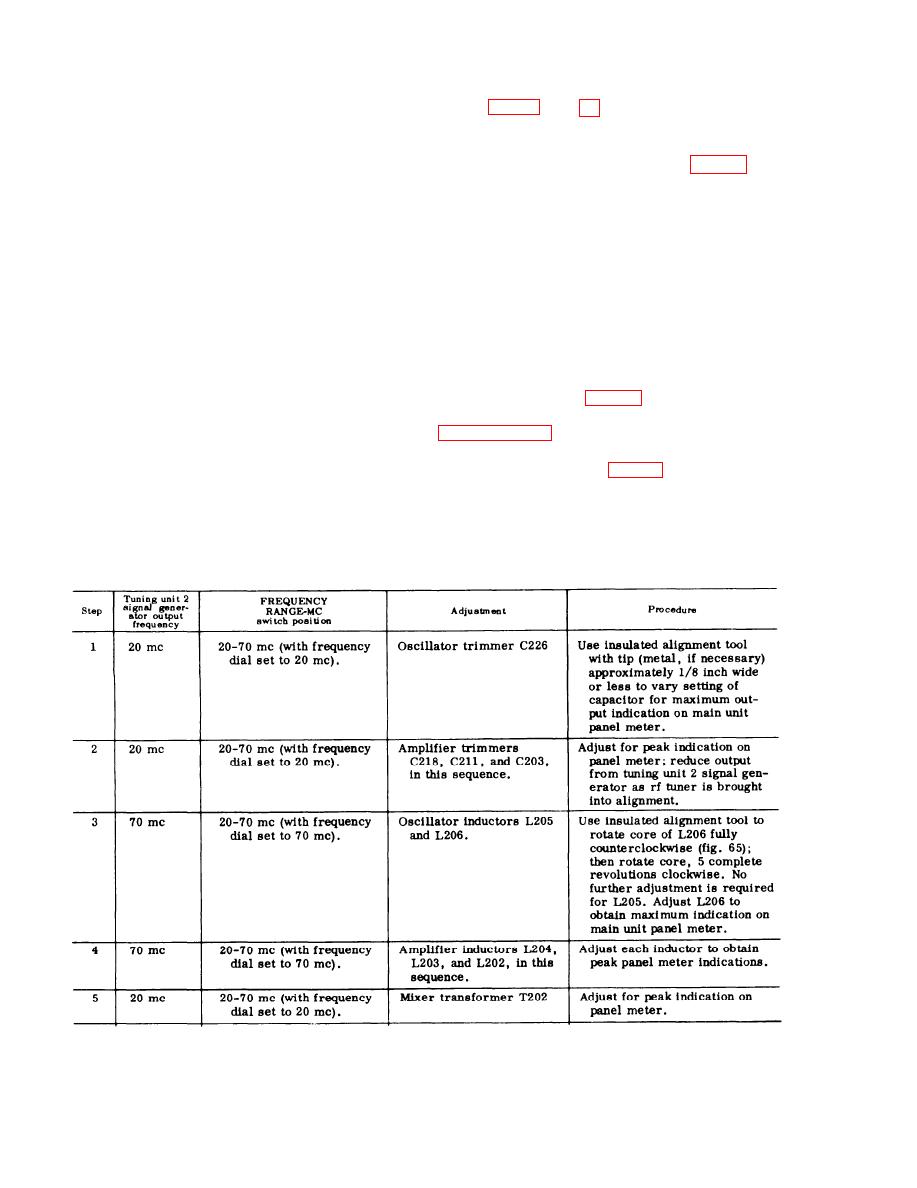
Alignment of Rf Tuner Section, Tuning Unit 2 |
|
||
| ||||||||||
|
|  91. Alignment of Rf Tuner Section,
tuning wand into the magnetic field
Tuning Unit 2
of the coupling loops such as the
f i e l d created by rf energy in the
v i c i n i t y of L401-L402, or L404-
L405. Observe the change in meter
tuner section of tuning unit 2 (fig. 65) re-
indication. An i n c r e as e in the
quire squeezing or spreading turns of un-
m e t e r indication shows the need
insulated wire. Never touch these induct-
ances with the bare fingers while operating
for reducing the coupling between
power is applied, since B+ potentials of
the pickup loops. This effect is ob-
105 volts and 150 volts are present. Always
tained by farther spacing b e t w e e n
u s e a well-insulated pair of pliers or
s i m i l a r tool for squeezing or spreading
t h e primary and . the secondary
the turns of wire. Also be careful to avoid
loops l
s h o r t - c i r c u i t i n g one t u r n of wire to
(2) Insert the powdered iron core end
another.
of the wand into the magnetic field
a. Align the rf tuner while tuning unit
surrounding the pickup loops under
2 is operating outside the main unit. Use
t h e test harness (fig. 46), with the front
measurement, and o b s e r v e the
panel control set to the positions listed in
change in meter indication. An in-
crease in meter indication now
b. Remove the cover from the exterior
shows the need for increasing t h e
side of the rf tuner (fig. 64).
coupling between the pickup loops.
c. Connect the output of the tuning unit 2
signal generator, through Cord CG-55B/U
T h i s effect is obtained by closer
supplied with the signal generator, to the
spacing between the primary and
main unit front panel SIGNAL INPUT jack.
Proceed as directed in the following chart:
s e c o n d a r y loops.
200
|
|
Privacy Statement - Press Release - Copyright Information. - Contact Us |
