 |
|||
|
|
|||
|
Page Title:
Figure 87. Multimeter, Remote ME-204/URM-86, parts location diagram. |
|
||
| ||||||||||
|
| 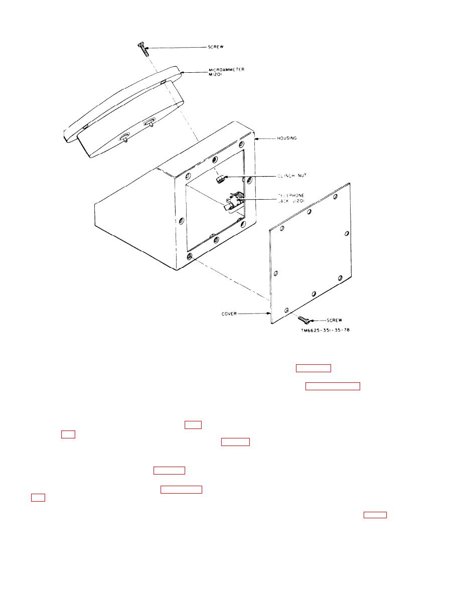 Figure 87. Multimeter, Remote ME-204/URM-86, parts location diagram.
formance checklist (para 43, TM 11-6625-
S902 known to be closed, and with
351-12). refer to the troubleshooting pro-
operating power applied to the main
cedures as outlined in paragraph 67c(1) of
unit, failure of the pilot lamp and
this manual. If power transformer T801 is
electron tubes in the tuning unit to
e s t a b l i s h e d as the defective part, be sure
b e illuminated indicates possible
to tag and identify the leads to the six ter-
trouble in the wiring of P901. Re-
minals before unsoldering; this will facil-
f e r to the schematic diagram (fig.
itate rewiring. Refer to the exploded view
continuity and isolation of the de-
o f replacement parts.
fect, and repair the cause of mal-
functioning.
79. Replacement of Parts, Main Unit
method of checking the operation of the ex-
N o t e : Several parts used in
the main unit have
ternal transformer is outlined in paragraph
s m a l l e r tolerances than those
used in most radio
equipment. All resistors, R741
through R749, and
11-6625-351-12. If the component fails to
R751 through R761, which are
part of the impulse
generator output controls S707
and S708 (fig. 53)
operate as indicated in the equipment per-
182
|
|
Privacy Statement - Press Release - Copyright Information. - Contact Us |
