 |
|||
|
|
|||
|
|
|||
| ||||||||||
|
|  67. Troubleshooting
the POWER receptacle on the main
unit front panel to the AC OUTPUT
a. Introduction. T h e t r o u b l e s h o o t i n g
receptacle on the front panel of the
chart (c below) is designed to supplement
TF-248/G.
t h e equipment performance checklist in
(6) I n t e r c o n n e c t t h e i n t e g r a l p o w e r
TM 11-6625-351-12. Proceed with the
c a b l e assembly on the TF-248/G
s t e p s of the following checklist until a
to a source of either 110-125 volts
s y m p t o m of trouble appears. Take cor-
or 220-250 volts, 50-400 cps. If the
rective action to remedy the trouble before
p o w e r source is 110-125 volts ac,
proceeding with the next step.
place the 120V-240V switch on the
Caution: If operational symptoms are not
external transformer front panel to
known or if they indicate the possibility of
the 120V position. This action will
short circuits within the equipment, make
deliver nominal 117 volts ac power,
the short circuit checks described in para-
f r e e of powerline disturbances, to
the test set. However, if the avail-
b. Conditions of Troubleshooting. Set Up
able power source is 220-250 volts
the equipment for the troubleshooting pro-
a c , place the 120-240-volt switch
cedure below as follows:
on the external transformer to the
(1) Remove the main unit from its in-
2 4 0 V position. This action causes
s t r u m e n t case (para 40b, item 12,
the TF-248/G to function as a 2 to
T M 11-6625-351-12).
1 stepdown ratio transformer.
(2) Remove the tuning unit under test
(7) Set the front-panel controls as di-
f r o m the tuning unit compartment
rected in the starting and calibrat-
of the main unit.
i n g procedures, TM 11-6625-351-
(3) R e m o v e the dust cover from the
12.
t u n i n g unit under test (para 64c).
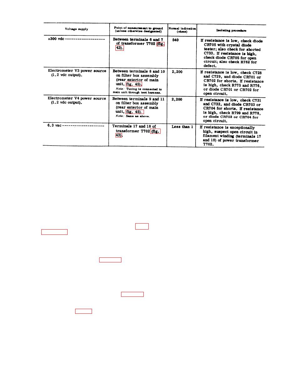
C . Troubleshooting Charts.
(4) U s e the test harness to intercon-
N o t e : Perform the operations in the equipment
nect the tuning unit and the main
performance checklist (TM 11-6625-351-12) before
unit (fig. 46).
u s i n g this chart, unless trouble has already been
(5)' Use Cable Assembly, Power, Elec-
localized.
t r i c a l CX-6680/U to interconnect
(1) T F - 2 4 8 / G .
107
|
|
Privacy Statement - Press Release - Copyright Information. - Contact Us |
