 |
|||
|
|
|||
|
Page Title:
Section Il. TROUBLESHOOTING TEST SET |
|
||
| ||||||||||
|
|  Section Il. TROUBLESHOOTING TEST SET
66. Checking B+ and Filament Circuits
sistance readings shown in figures
for Shorts
condition.
Caution: Do not attempt removal of parts
c o Measurements.
before reading the instructions in para-
(1) T o take resistance readings from
the terminals of electron tube
a. When to Check. When any of the fol-
s o c k e t s (XV704, XV705, XV708,
l o w i n g conditions exist, check for short
and XV709) mounted on the upper
circuits and clear the troubles before
deck of the main unit, remove the
applying power:
tube from its socket and insert the
(1) T h e nature of the abnormal sym-
multimeter test prods into the
tom is not known.
designated terminals (fig. 42).
(2) T h e abnormal symptoms reported
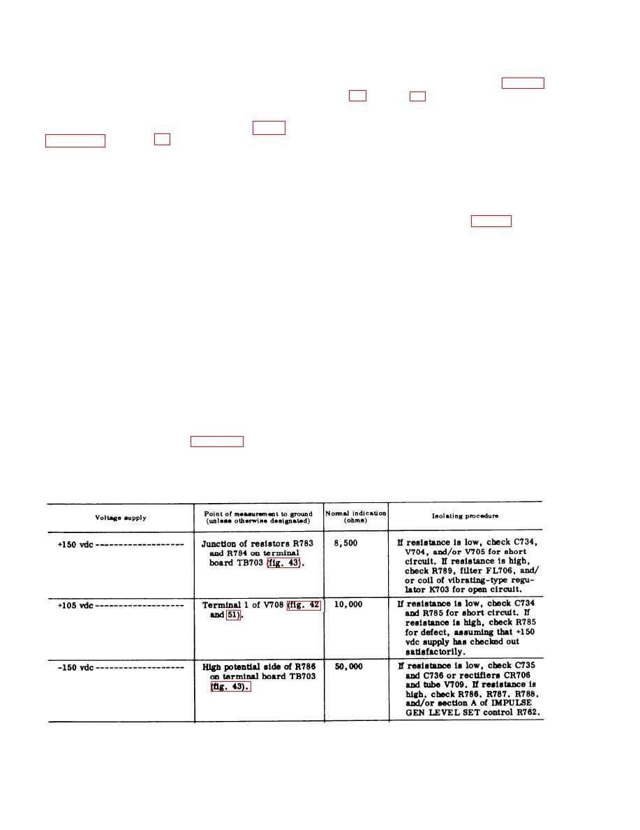
(2) M a k e the resistance measure-
from operational tests indicate
ments indicated in the chart below.
p o s s i b l e power supply troubles.
A difference of more than 20 per-
(3) The insulation of filament wiring on
c e n t from readings in the chart
t h e underside of the main unit or
s h o u l d be considered abnormal. If
t u n i n g units s h o w s e v i d e n c e o f
a b n o r m a l readings are obtained,
m e l t i n g or charring. This condi-
p e r f o r m the isolating procedures
t i o n usually indicates a short cir-
listed in the chart. When the faulty
c u i t in filament wiring or an in-
p a r t is found, repair the trouble
ternal short in the heaters of
before applying power to the unit.
e l e c t r o n tubes.
When replacing faulty rectifiers or
b. Conditions for Tests. To prepare for
tubes in the power supply, always
the short circuit tests, proceed as
check for shorted filter capacitors.
i n s t r u c t e d below.
Frequently a faulty filter capacitor
Warning: Do not plug in the power cord
will cause the rectifier to go bad.
while taking short circuit measurements.
I n such cases, replace the faulty
(1) Remove the main unit from its
capacitor before installing the new
i n s t r u m e n t case (para 40b, item
rectifier.
12, TM 11-6625-351-12).
N o t e : Be sure to connect the negative test prod
(2) Unless otherwise indicated, re-
of the multi meter to chassis ground for checking
move tuning unit 1 from the main
the positive power supplies. Reverse the test prods
unit compartment, since the re-
for checking the negative power supplies.
106
|
|
Privacy Statement - Press Release - Copyright Information. - Contact Us |
