 |
|||
|
|
|||
|
Page Title:
Minor Electrical Components for Use with All Tuning Units |
|
||
| ||||||||||
|
| 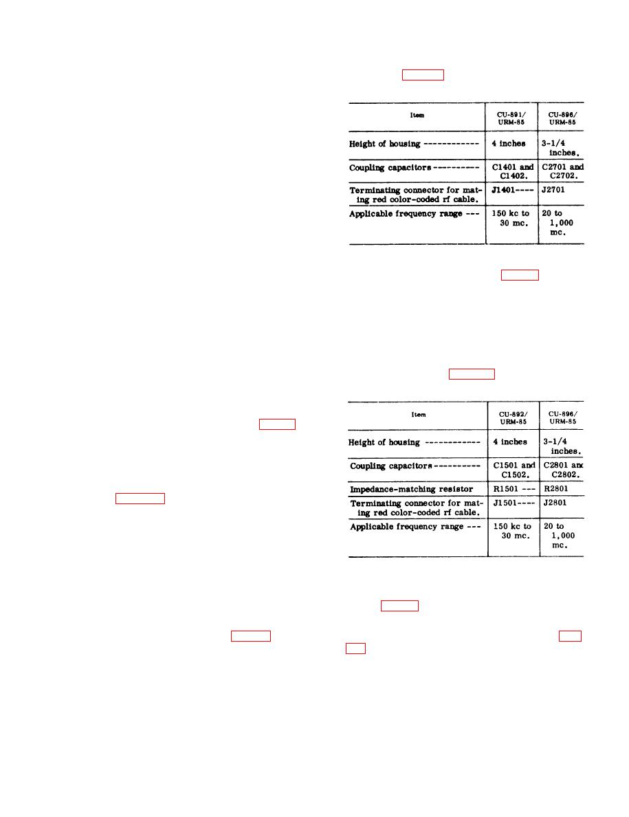 f r e q u e n c y range. The CU-896/URM-85 is
of a 90 angle corner reflector. This
i d e n t i c a l in function with the CU-891/
r e f l e c t o r , illustrated in TM 11-6625-351-
URM-85 (para 59d), but differs in the fol-
12, provides a power gain of approximately
l o w i n g physical respects:
1 0 - d b throughout its frequency range. To
o b t a i n a proper impedance match to the
two 50-ohm coaxial cables that connect the
d i p o l e s (at one end of the boom) to the
balun (at the opposite end of the boom), an
antenna impedance of 100-ohms is re-
quired. This impedance is obtained with a
d i p o l e - t o - r e f l e c t o r corner spacing of 0.4
wavelength. Since the wavelength changes
a s the test set is tuned to various fre-
q u e n c i e s in the 400- to 1,000-mc range,
t h e spacing between the dipoles and the
c o r n e r of the reflector must be adjusted.
One side of the megacycle ruler, supplied
a s a minor component, is calibrated to
h. Coupler, Radio Frequency Interfer-
i n d i c a t e the proper spacing between the
plane of the dipoles and the corner of the
C V - 8 9 7 / U R M - 8 5 (another capacitive type
pickup device) is used to conduct rf sig-
r e f l e c t o r ; the other side of the ruler is
n a l s or noise interference from approxi-
c a l i b r a t e d to indicate the proper length
m a t e 500-ohm impedance 2-wire audio-
of each dipole arm for the particular
signal or electrical powerlines in the
frequency under measurement. Each
2 0 - to 1,000-mc frequency range. This
d i p o l e is of telescopic construction and
m a y be extended from its minimum col-
c o u p l e r is identical in function with the
l a p s e d length of 2-1/4 inches to a max-
CU-892/URM-85 (para 59e), but differs in
the following physical respects:
imum 1 e n g t h of approximately 6-1/2
inches.
f . Probe Magnetic Interference Meas-
m a g n e t i c field probe is used to localize
m a g n e t i c field components of rf inter-
f e r e n c e in the 20- to 1,000-mc frequency
r a n g e . This signal pickup device is iden-
tical in function with the MX-3409/URM-
85 (para 59c) which is used for the 150-
k c to 30-mc frequency range. Because of
the higher frequency electromagnetic
fields employed, only 1 turn of wire in the
l o o p end of the probe is required. Con-
n e c t o r plug P3001 mates the red color-
c o d e d coaxial cable of Cable Assembly
61. Minor Electrical Components for
S e t , Electrical MX-3410/URM-85, so that
Use with All Tuning Units
the path of continuity to the main unit SIG-
NAL INPUT jack is completed.
g. Coupler, Radio Frequency Interferw-
a. P r o b e, Electrical Field, Intelfer-
8 9 6 / U R M - 8 5 (a capacitive-typd pickup
d e v i c e ) is used to conduct rf signals or
localize the electric field component of rf
n o i s e interference signals from 50-ohm
i n t e r f e r e n c e over the complete frequency
i m p e d a n c e 2-wire audio-signal or elec-
range of the test set from 150-kc to 1,000-
t r i c a l powerlines in the 20- to 1,000-mc
mc. This signal pickup device consists of
87
|
|
Privacy Statement - Press Release - Copyright Information. - Contact Us |
