 |
|||
|
|
|||
|
|
|||
| ||||||||||
|
|  t e r m i n a l on the tuning unit con-
d u c e s a basic frequency of approximately
n e c t o r are filter and interconnect-
70-cps. The output from this oscillator is
ing points in this dc potential path.
u s e d as the input to impulse generator
(2) T h e potential present at the junc-
d r i v e r stage V703B.
(1) Plate circuit. The plate, pin 6, of
tion. of the SLIDEBACK control (in
the tuning unit) and voltage-divider
V703A receives B+ potential
r e s i s t o r R710 is coupled through
t h r o u g h voltage-dropping resistor
r e s i s t o r R709, wafer switch S702
R728 and the ON position of switch
r e a r , section X, and filter FL702
S705. B+ potential is removed from
to the negative terminal of the
the plate of the stage when S705 is
m e t e r . In the METERED SLIDE-
set to the OFF position. Resistors
BACK position of the function
R726 and R727 function as bleeders
f o r the +150-volt output from the
s w i t c h , R709 serves as the new
m e t e r multiplier resistor.
power supply, in the OFF position
of the switch.
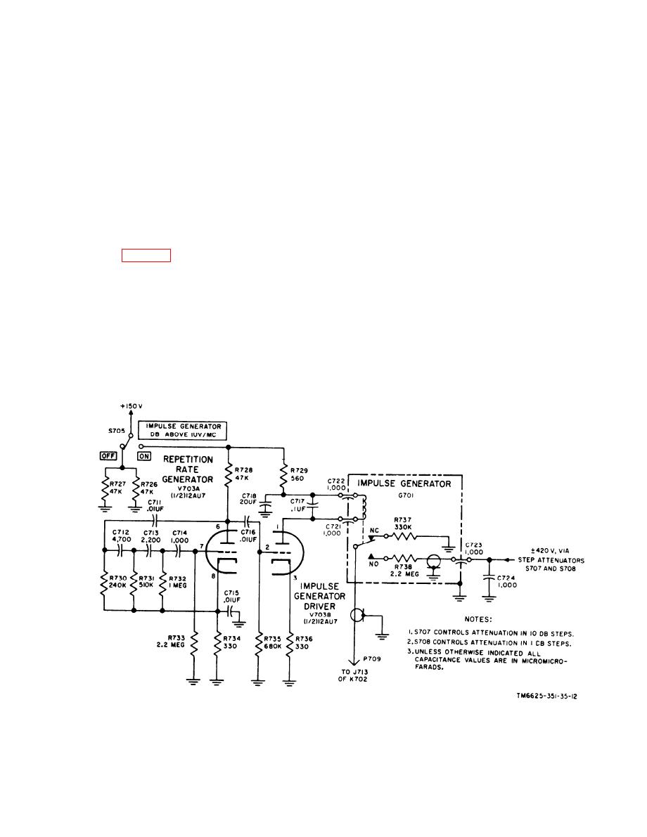
23. Impulse Generator Circuit
(2) Cathode circuit. R e s i s t o r R 7 3 4 ,
b y p a s s e d by capacitor C715, de-
v e l o p s the cathode bias for the
T h e impulse generator circuit consists
o f repetition rate generator V703A, im-
stage. The B+ potential at the junc-
tion of the plate, pin 6, and drop-
pulse generator driver V703B, and impulse
generator G701. A detailed description of
ping resistor R728, is blocked from
reaching the grid, pin 7, by capac-
t h e s e circuits is given in the following
itor C711. Therefore, V703A oper-
subparagraphs.
a t e s as a self-biased stage.
a. Repetition Rate Generator V703A. T h e
(3) Grid circuit. A f r e q u e n c y - d e t e r -
repetition rate generator is one section of
a dual triode, which functions as a self-
mining network, which consists of
r e s i s t o r s R730, R731, and R732
e x c i t e d phase-shift oscillator that pro-
Figure
13.
Impulse
generator
circuit,
simplified
schematic
diagram.
31
|
|
Privacy Statement - Press Release - Copyright Information. - Contact Us |
