 |
|||
|
|
|||
|
Page Title:
Figure 9. Cathode follower and meter circuit, CW PEAK position of function switch. |
|
||
| ||||||||||
|
| 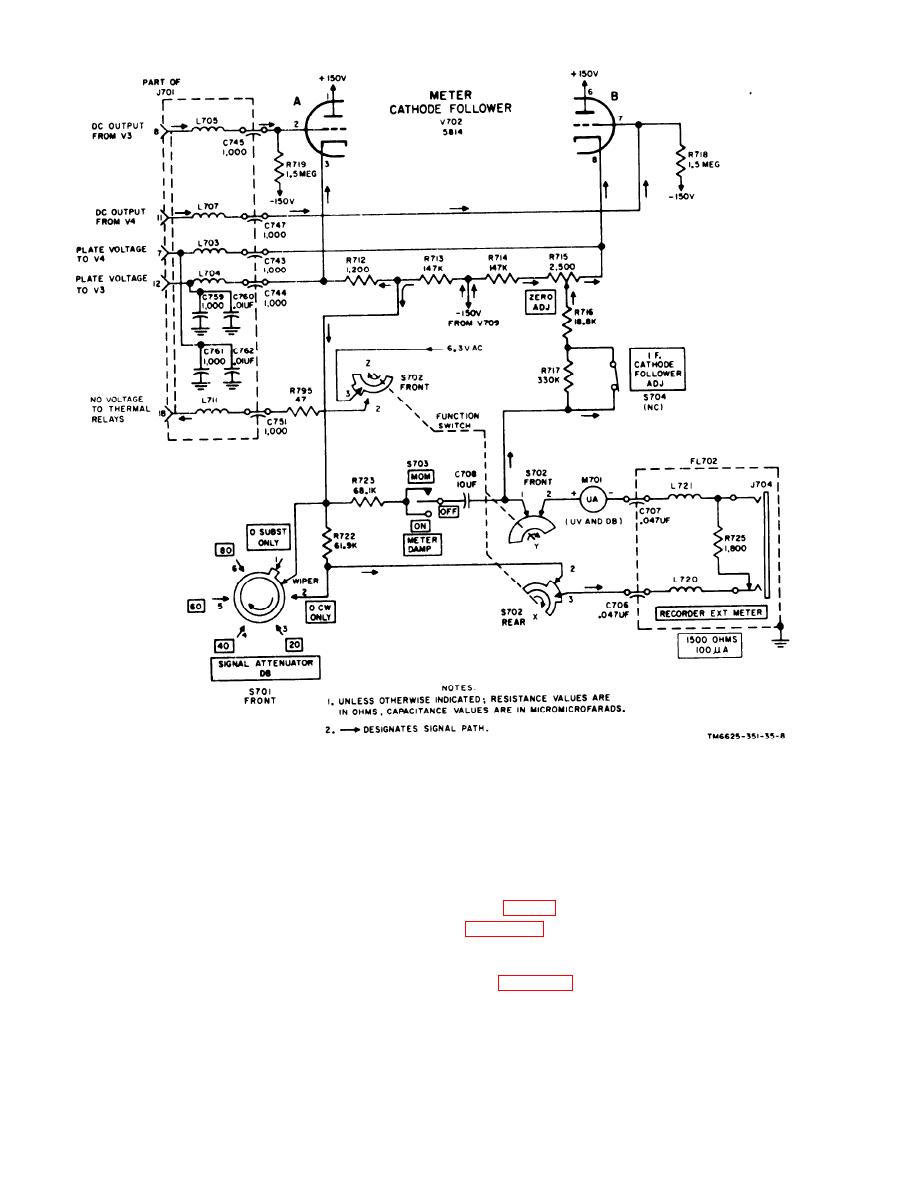 Figure 9. Cathode follower and meter circuit, CW PEAK position of function switch.
m e t e r cathode follower V702 while eqti-
J701. With a tuning unit plugged into the
izing the voltage across the metering cir-
m a i n unit, terminal 1 of the mating con-
cuit with ZERO ADJ control R715.
nector on the tuning unit couples this -150-
v o l t potential (with reference to chassis
21. PULSE PEAK Position of Function
ground) to the if. amplifier bus. Fixed re-
Switch
s i s t o r R708 is shorted out of the circuit
b y terminal 3 of the switch, and permits
the full output of voltage regulator V709,
function switch S702 in PULSE PEAK posi-
in the negative power supply, to be applied
tion is similar to that in ZERO ADJ posi-
to the if. bias bus. A high negative voltage
t i o n (para 20), except for the following
is developed in the if. bias bus which cuts
differences:
off the complete if. amplifier, and assures
a. S702 Rear, Section X. The s w i t c h
t h a t no metering signal can pass through
26
|
|
Privacy Statement - Press Release - Copyright Information. - Contact Us |
