 |
|||
|
|
|||
|
Page Title:
Figure 11. Cathode follower and meter circuit, PULSE PEAK position of function switch. |
|
||
| ||||||||||
|
| 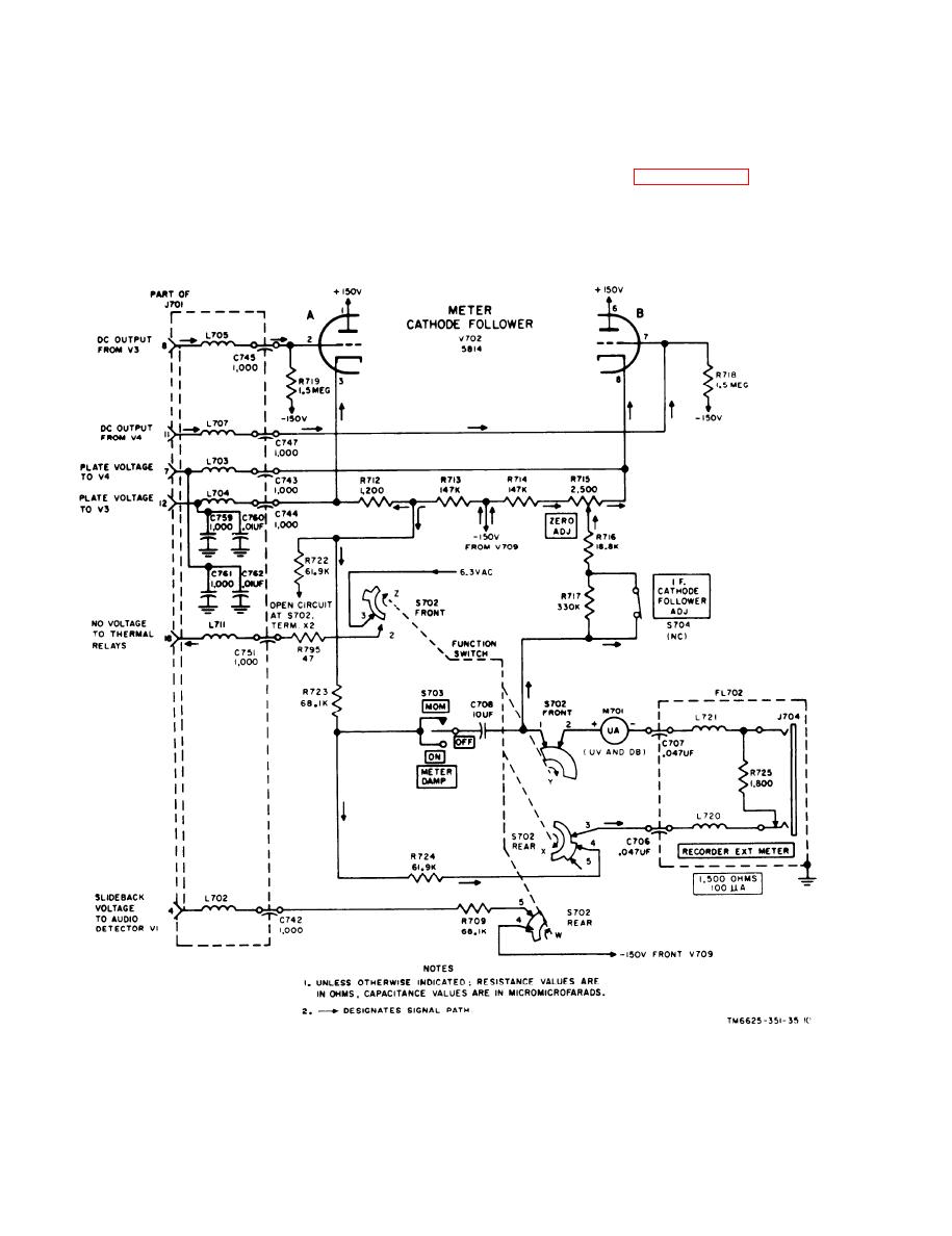 c o n t a c t between terminals 1 and 2 con-
CW PEAK position. This loss in meter
tinues to exist. Therefore, the signal path
sensitivity is taken into account in the de-
from the positive terminal of meter M701
sign of the instrument. The dc signal from
to the cathode of V702B and the positive
t h e series multiplier resistors is coupled
s o u r c e in the power supply is identical
t h r o u g h S702 (rear (terminals 3 and 4))
with that described in paragraph 18 b.
and filter FL702 to the negative terminal
c. S702 Front, Section Z. The s w i t c h
of meter M701.
wafer has been rotated 90 clockwise from
b. S702 Front, Section Y. The s w i t c h
i t s original CW AVERAGE position. The
wafer has been rotated 90 clockwise from
contact between terminals 2 and 3 remains
i t s original CW AVERAGE position, but
Figure 11. Cathode follower and meter circuit, PULSE PEAK position of function switch.
28
|
|
Privacy Statement - Press Release - Copyright Information. - Contact Us |
