 |
|||
|
|
|||
|
Page Title:
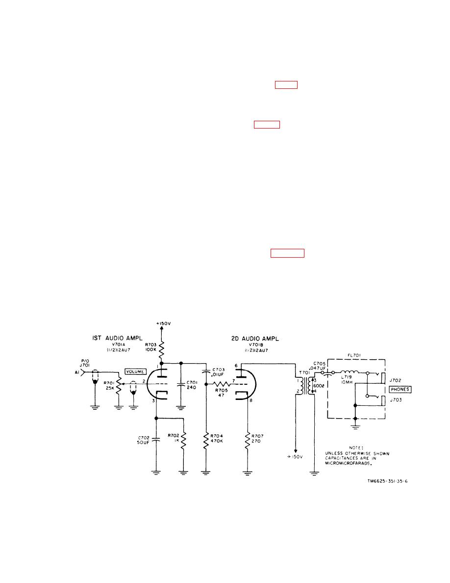
Audio Amplifier, Stage Analysis |
|
||
| ||||||||||
|
|  p o s i t i v e or negative output pulses
generator which functions as a
f r o m impulse generator G701 can
s t a n d a r d for calibrating purposes.
be observed when performing noise
(2) T h e high side of variable resistor
measurements.
R 7 6 2 A is connected to the -150-
volt output of regulator V709. The
16. Audio Amplifier, Stage Analysis
low side of R762A is connected to
c h a s s i s ground. When POLARITY
switch S709 is set to its minus (-)
A u d i o amplifier V701 is a dual triode,
position, the variable arm of R762A
which receives its input signal from audio
w i l l be connected to the positive
d e t e c t o r V1 in the electrometer assembly
300-volt output at the plate of volt-
( f i g . 1) and delivers its output signal to
age regulator V706. The circuit
o n e or two headsets. The two sections of
a r r a n g e m e n t is similar to that de-
V701 function as two separate amplifiers,
scribed in (1) above, but is of
a s described below.
o p p o s i t e polarity. A total usable
a. First Audio Amplifier V701A. T h e
output of 450-volts can be obtained
audio voltage at terminal Al of connector
by adding the -150-volts (from the
J701 is applied to the grid resistor, which
high side of R762A to chassis
consists of VOLUME control R701, through
g r o u n d ) to the +300-volts (from
a shielded cable. When the meter is used
chassis ground to the positive out-
as the indicating device for the signal under
put of V706 and V707). A variation
measurement, the full output of the audio
of 150-volts is obtained by rotating
d e t e c t o r in the electrometer assembly is
the arm of IMPULSE GEN LEVEL
applied to the first audio amplifier. When
S E T control R762. The setting of
t h e slideback technique of operation is
t h e potentiometer determines the
used (para 22), the setting of the SLIDE-
c h a r g i n g voltage, applied through
B A C K control applies a negative bias to
1 0 - d b step coarse attenuator con-
the plate of the audio detector stage. Under
trol S708 to impulse generator
this condition, only the peaks of the signal
G701 (1) above).
under measurement, with an amplitude
(3) The positive and negative positions
higher than the detection level set by the
of POLARITY switch S709 are pro-
SLIDE BACK control, will be heard in the
vided so that the effects of either
Figure 7. Audio amplifiers V701A and V701B, simplified schematic diagram.
21
|
|
Privacy Statement - Press Release - Copyright Information. - Contact Us |
