 |
|||
|
|
|||
|
|
|||
| ||||||||||
|
| 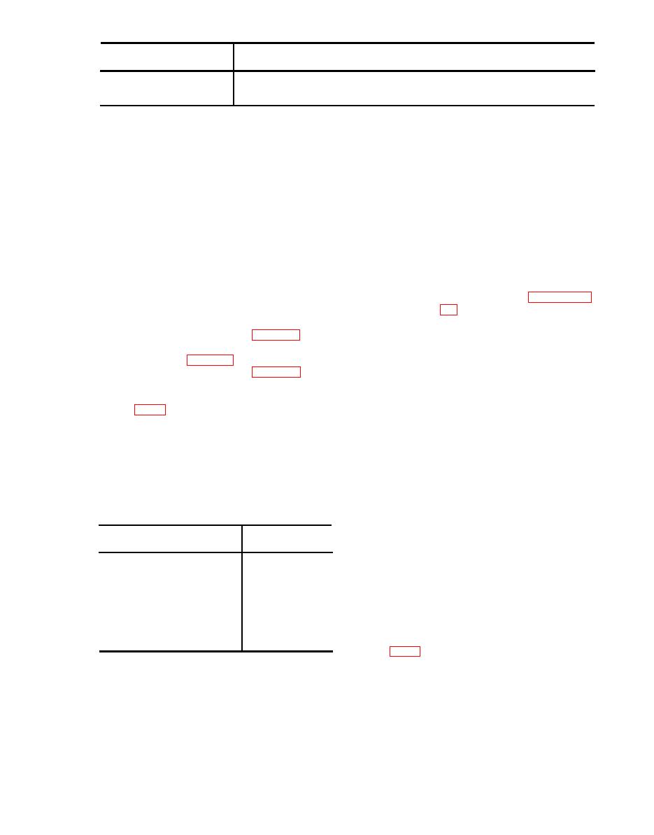 Control
Function
Microphone switch ---------
Normally, a two-position switch. In one position, energizes the transmission cir-
cuits; in the other, deenergizes the transmission circuits.
Light control - - - - - - - - - - - - -
Varies the brilliance of the panel lamps on the control unit.
a. The transponder set is operated re-
(2) P l a c e the master control in the
motely from the aircraft cockpit through
STBY position. The pilot light
the use of the control unit. Depending on
should light.
the settings of the various controls, the
Note: If the pilot light does not light,
press the test button. If the pilot light still
transponder set can be operated to reply
fails to light, either the light is burned out
to interrogation signals with normal, sif,
or power is not reaching the transponder
or civil pulse codes; to provide identifi-
set.
c a t i o n - p o s i t i o n reply codes; to transmit
(3) Adjust the pilot light to the desired
automatically, emergency reply codes; and
brilliance by opening or closing
to provide personal identification (MODE
the lens shutter.
(4) Allow the transponder set to warm
2) or flight leader identification (MODE
up from 3 to 5 minutes.
3).
(5) F o l l o w the procedures in para-
b. T O operate the equipment for any par-
ticular type of operation, perform the fol-
graphs 22 through 27 for the de-
l o w i n g procedures:
sired type of operation.
(1) `Starting procedure (para 20).
Note: The control unit is provided with
illumination from the rear of the front panel.
(2) Procedure for desired type of op-
This light and the pilot light, are not go-
eration (para 22 through 27).
no-go indicators of the receiver-transmitter
but only indicate that power is reaching
(3) Stopping procedure (para 28).
the equipment.
CodeNumber
Caution: Be careful when rotating the
s e c o n d digit selectors on MODE 1 and
For tactical purposes, IFF code assign-
MODE 3 controls to their extreme clock-
ments are continuously being changed. The
wise and counterclockwise positions. Use
c o d e s consist of two- or four-digit num-
o f excessive force can cause damage to
bers which indicate the correct settings of
the switching mechanism.
c o d e controls or switches. The trans-
a. Preliminary. Set the various controls
ponder set converts this code to a coded
as follows:
pulse train. For modes 1 and 3, the as-
signed code numbers are two-digit num-
Control
Position
b e r s which are n o r m a l l y set up by the
p i l o t with visual control indicators. For
Master control -------------
OFF.
AUDIO switch --------------
OFF.
m o d e 2, the assigned code number is a
I/P switch -----------------
OFF.
four-digit number which is preset b e f o r e
MODE 2 switch -------------------
OFF.
MODE 3 switch --------------------
f l i g h t . This is n o r m a l l y done by the or-
OFF.
MODE 1 code control -------
To read 00.
ganizational repairman or crew chief.
MODE 3 code control -------
To read 00.
NORMAL.
Function control ----------------
Master power on-off switch --
Off.
AN/APX-44 circuit breaker--
Off.
(fig. 6 )
b. Starting.
Note: When the function control is set in the NOR-
MAL position, all preset code combinations will be
(1) Place the master power on-off con-
disabled on all modes and a standardized reply will
t r o l to on and energize the AN/
be automatically transmitted by the transponder set
A P X - 4 4 circuit breaker.
when interrogated.
|
|
Privacy Statement - Press Release - Copyright Information. - Contact Us |
