 |
|||
|
|
|||
|
|
|||
| ||||||||||
|
|  TM 11-5825-271-34
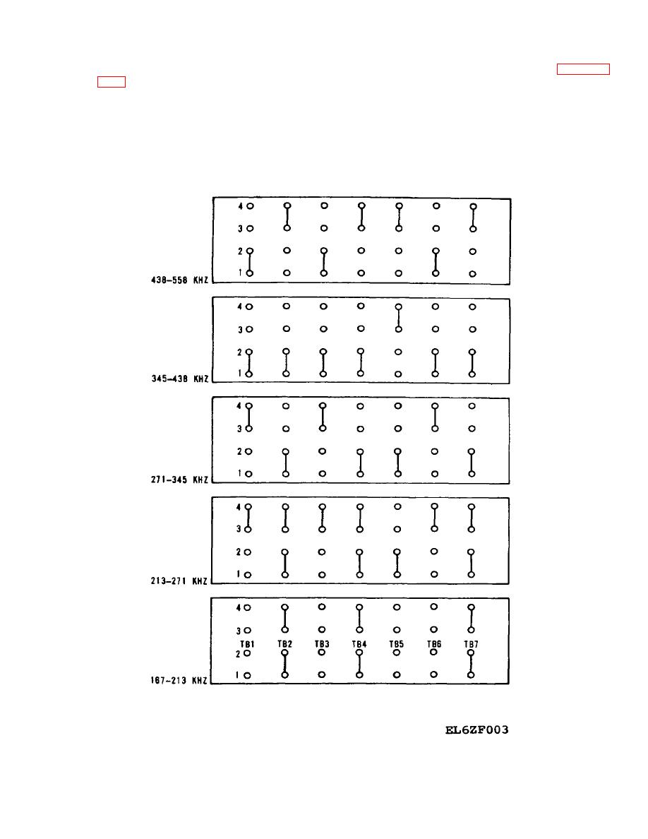
525 kHz in five strapping configurations, see figure 2-3.
2-18. RF Filter A1A5
The network formed by R1, R2 and C1 provides damping
(fig. FO-8)
for transients generated in the pa module A1A4.
a. The purpose of the rf filter AlA5 is to attenuate
Transformer T1 provides impedance matching between
the harmonic components in the input at J1 from the pa
the rf filter AlA5 and the pa module A1A4. Network
module AlA4. The rf filter AIA5 consists of two 1/4-
comprising R3/R4, L9/L10 and C6/ C7 provides a
wavelength sections which are cascaded to produce a
terminating impedance for the out-of-band frequencies.
five-pole, 1/2-wavelength filter.
This is necessary because the antenna system presents
b. The rf filter AlA5 contains 10 programming
a very high impedance to frequencies outside the
straps which permit selection of appropriate component
operating band.
values to cover the operating range of 190 to
Figure 2-3. RF Filter Strapping.
2-8
|
|
Privacy Statement - Press Release - Copyright Information. - Contact Us |
