 |
|||
|
|
|||
|
Page Title:
Table 2-1. Transmitter Interconnect Cables |
|
||
| ||||||||||
|
|  TM 11-5820-918-13
Transmitter Interconnect Cables
Cable
BR cable
From
To
Remarks
designation
part number
W1
3J3
8120-4000-72
lJ2
Control of 4011 direct/diplex
relay and 4011 RF power sensor
output to 1024
W2
3J5
1024 AC Power in from 4011
lJ1
8120-5000-72
W3
2J4
3J4
5018 AC Power in from 4011
8120-5001-48
W4
AC
3J6
AC Line Power In
8120-0201-120
Power
W5
2J3
5018 RF (100W) Output to 4011
3J2
8120-2002-48
W6
3J1
2J2
5018 RF (10W) Output to 4011
8120-2004-48
W7
1024 RF Output to 5018 RF Input
2J1
8120-2004-48
lJ3
Connection from the user's communications transmitter to the 4011 front panel is into J8
HN coaxial connectors. The mating cable should use an HN plug, such as UG-59 or
equivalent.
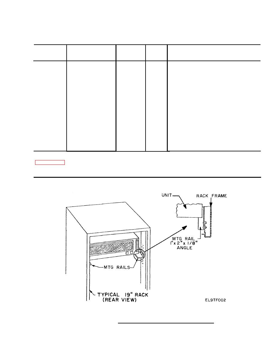
FIGURE 2-1. Rack Mounting for Transmitter Units.
|
|
Privacy Statement - Press Release - Copyright Information. - Contact Us |
