 |
|||
|
|
|||
|
|
|||
| ||||||||||
|
|  TM 11-5820-917-13
5-22. To make the receiver adjustment, the direction and rate of drift on the CRT
are determined. Then, if' the display is drifting downward, the front panel fine
control (STD ADJ) is turned clockwise; if the display is drifting upward, the STD
ADJ control is turned counter-clockwise. One full turn of the front panel STD
ADJ control will compensate for a drift of approximately 10% of CRT height per 24
hours for 2-30 MHz sweep, or 0.5 milliseconds per 24 hours. (One full turn will
compensate for a drift of 5% of CRT height per 24 hours for 2-16 MHz sweep,)
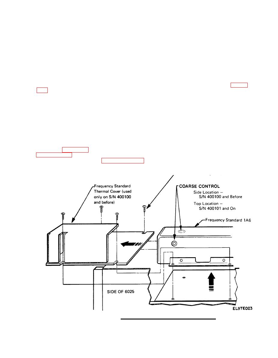
If the STD ADJ control adjustment range is insufficient (at physical limits which
are 20 turns end to end) to make the correction, it should be recentered, and the
adjustment made on the course control located on the 6025, assembly 1A6 (figure
STD ADJ control. For coarse control adjustment, turn counter-clockwise if dis-
play is drifting down; turn clockwise if display is drifting up. One turn of the
coarse adjustment control will compensate for a drift of 100% of CRT height per 24
hours (5 milliseconds per 24 hours) for a 2-30 MHz sweep, or 50% of CRT height for
2-16 MHz sweep.
zation signals are adjusted following replacement of circuit elements or when dis -
continuities are observed in the position or linearity of the display. The bright-
ness control for the CRT is on the front panel and is an operator adjustment.
(Refer to Section 3, and check brightness adjustment). The schematic diagram of
adjustments described in paragraphs 5-24 thru 5-27, the following disassembly
actions must be performed:
Crystal Oscillator Frequency Adjust.
|
|
Privacy Statement - Press Release - Copyright Information. - Contact Us |
