 |
|||
|
|
|||
|
Page Title:
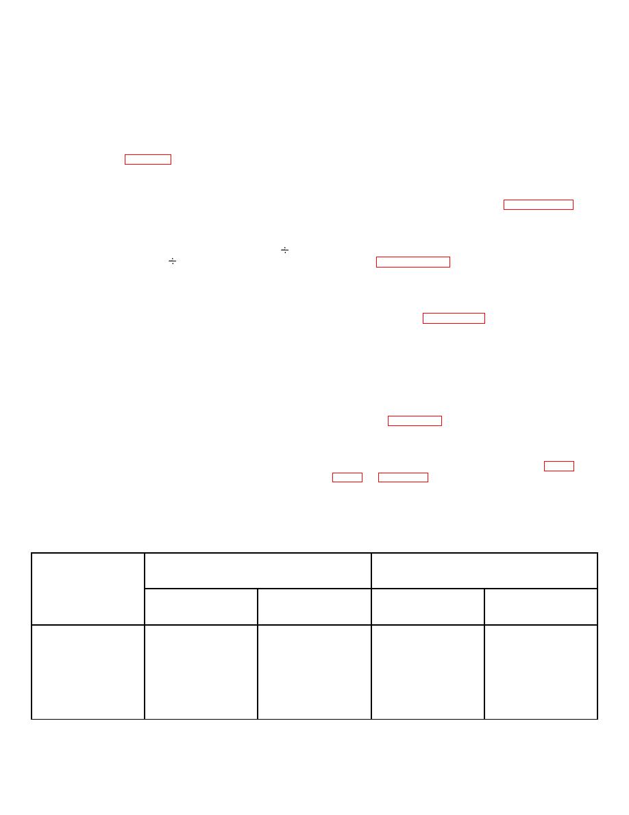
Table 4-2. VCO and Radio Control Frequency Versus VCO Band |
|
||
| ||||||||||
|
|  TO 31R2-2GRC171-2
TM 11-5820-815-14
NAVELEX 0967-LP-544-5010
midband, or high-band vco generates the synthesizer
4-67. The following details operation of individual
output signal which appears at the transmit rf output or
functions of the synthesizer. Unless otherwise speci-
receive injection output. The band decoder processes
fied, reference designators apply to components of
10- and 100-MHz frequency select informa- tion from the
frequency synthesizer module A2.
radio control and transmitter key line (key 1) information
to enable one of the three voltage- controlled oscillators
4-68. BAND DECODERS.
The synthesizer uses
in accordance with table 4-2. The power splitter couples
NAND and NOR gate logic to decode transmitter key line
the vco signal to the synthesizer output and to the
information and 10-, 20-, 40-, 80-, and 100-MHz radio
variable divider input and provides isolation between the
control frequency select information into frequency band
two paths. Rf amplifiers amplify the vco signal to the
information. The low-band decoder (figures FO-19 and
proper level for receiver injection and transmitter
4-2) provides a logic 1 output voltage through resistor
excitation. Key 2 controls the transmit/receive switch to
A2A7R18 to enable the low-band vco, A2A1, whenever
select either the receive injection output during receive
the radio control is set below 250 MHz in transmit mode
mode or the transmit rf output during transmit mode.
or below 280 MHz in receive mode. The high-band
The regenerative divider, 2-modulus prescaler,
A
decoder (figures FO-19 and 4-3) provides a logic 1
programmable counter, and Np programmable counter
output voltage through resistor A2A7R20 to enable the
form the variable divider which divides (as described
high-band vco, A2A3, whenever the radio control is set to
previously) the output of the power splitter by N to give
320 MHz or above in transmit mode or to 350 MHz or
12.5 kHz at the frequency/phase detector when phase
above in receive mode. The midband decoder (NOR
locked. The reference divider divides the output of the
gate A2A7U21B of figure FO-19) decodes the outputs of
3.2-MHz frequency reference by 256 to provide a 12.5-
the low- and high-band decoders to provide a logic 1
kHz reference signal at the reference input of the
voltage through resistor A2A7R19 to enable the midband
frequency/phase detector.
The frequency/ phase
vco, A2A2. The mid- band decoder output is only logic 1
detector compares the two signals and generates an
when the low- and high-band decoder outputs are logic
asymmetrical output waveform whose duty cycle is
0. This occurs when the radio control frequency is set
proportional to the phase difference between the two
between 250 and 319.975 MHz for transmit mode and
signals. The low-pass filter filters the waveform into a dc
between 280 and 349.975 MHz for receive mode. Truth
tuning voltage that is proportional to the duty cycle. The
tables for the low-band decoder and high-band decoder
tuning voltage drives the vco to the proper frequency. In
are given in figures 4-2 and 4-3 respectively.
the variable divider, 30-MHz decode and transmit/receive
control logic decreases the division ratio by 30 whenever
4-69. VOLTAGE-CONTROLLED OSCILLATORS.
the transmitter is un-keyed to decrease the synthesizer
The low-band, midband, and high-band voltage-
output frequency (receive injection output) by 30 MHz.
controlled oscillators, A2A1, A2A2. and A2A3 (figure
The lock monitor compares the frequency reference to
the variable divider output to provide a pll fault logic
inductance value of L1 and capacitance value of C4.
signal when- ever the synthesizer is not phase locked.
These components allow the oscillators to be adjusted to
cover the three different frequency ranges of the
Table 4-2. VCO and Radio Control Frequency Versus VCO Band
RRADIO CONTROL
VCO FREQUENCY
FREQUENCY
(MHz)
ENABLED
(MHz)
VCO
XMT MODE
RCV MODE
XMT MODE
RCV MODE
LOW-BAND
225.000 thru
225.000 thru
225.000 thru
195.000 thru
249.975
279.975
249.975
249.975
MIDBAND
250.000 thru
280.000 thru
250.000 thru
250.000 thru
319.975
349.975
319.975
349.975
HIGH-BAND
320.000 thru
350.000 thru
320.000 thru
320.000 thru
399.975
399.975
399.975
369.975
4-13
|
|
Privacy Statement - Press Release - Copyright Information. - Contact Us |
