 |
|||
|
|
|||
|
Page Title:
Section IV. CALIBRATION AND ADJUSTMENT |
|
||
| ||||||||||
|
|  TM 11-5820-695-35
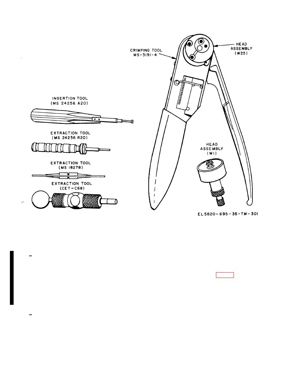
Figure 3-26. AN/GRC-144 connector repair tools.
Section IV. CALIBRATION AND ADJUSTMENT
procedure are not obtained, refer to the troubleshooting
3-54. General
charts (para 3-) for corrective action.
a.
This section contains procedures for
3-55. Calibration of Transmitter Meter 1A15A8M1
calibrating and adjusting the T-1054 (P)/GRC -144(V), T
-1054 (P)A/GRC -144 V), R-1467(P)/GRC-144(V), and
a.
Set POWER ON/OFF switch 1A15A8S3 on
R-1467(P)A/ GRC-144(V). The calibration procedures
are performed at periodic maintenance intervals (para 3-
meter panel assembly 1A15A8 (fig. 3-1) to OFF.
3) to maintain calibration accuracy of the transmitters
b.
Turn meter selector switch 1A15A8S4 on
and receivers metering circuits, or when troubleshooting
indicates that calibration is required. The adjustment
meter panel assembly 1A15A8 to OFF (TRANSIT).
procedures are performed when troubleshooting
indicates that an adjustment is required.
c.
Using a screwdriver, adjust the screw on the
front of meter 1A15A8M1 for a zero meter indication.
b.
All of the procedures contained in this
section assume that the AN/GRC144(V) is turned on
d.
Turn meter selector switch 1A15A8S4 on
and connected for normal operation at the start of each
meter panel assembly 1A15A8 to TEST LEAD (+).
procedure. If trouble is encountered during performance
of a procedure, or if the indications specified in the
Change 6
3-75
|
|
Privacy Statement - Press Release - Copyright Information. - Contact Us |
