 |
|||
|
|
|||
|
Page Title:
The 10 MHz divide-by-ten register stages Z2 through Z6 operate as a Johnson Counter |
|
||
| ||||||||||
|
|  TM 11-5820-695-35
flop type 950, pin 4 must be at a low (0-volt) level.
The output (divide-by-N pulses) from stage Z10 of the
When the registers state is 00000, only Z2 is
divide-by-eight registers is applied through output
conditioned by Z6 to be set; stages Z3 through Z6 are
inverter stage Z18 to fixed frequency divider 1A14A6
conditioned to be reset, but, since they are already
and to af phase error detector 1A14A3. If the count in
reset, their status is not changed. After Z2 has been set
the 1A14A5 registers was not programmed by the
its outputs condition Z3 to be set. The second incoming
thumbwheel switch settings (10 MHz, 100 MHz, and
negative-going count transition sets Z3 (00011); the
1000 MHz) and the control logic in variable 2 frequency
third negative-going count sets Z4 (00111); the fourth
divider 1A14A4, they would divide the count pulses by
negative-going count sets Z5 (011(11); and the fifth
80 (10 x 8). Both variable frequency dividers 1A14A4
negative going count sets Z6 (11111).
and 1A14A5 would divide the if output frequency from
1A14A2 by 16,000 (200 x 80) if they were not
programmed. The registers in 1A14A5 count down the
count pulses from 1A14A4 until the registers contain the
unique number (divide-by-eight register contains 111-
decimal 7 and divide-by-ten register contains 11110-
decimal 4). The binary to decimal relationships are
described later in this paragraph. Once the registers
contain the unique numbers, the reset enable signal is
applied to 1A14A4 to produce the initialize, inhibit, and
preload sequence (3 counts). The initialize signal from
1A14A4 insures that registers are at the required count
for setting in a number from the thumbwheel switches.
The inhibit signal from 1A14A4 prevents the divide-by-
eight register from accumulating a false count. The
preload signal modifies the count ((11111110) in the
registers in accordance with the 10 MHz, 100 MHz, 1000
MHz thumbwheel switch settings. The modified count in
Setting Z6 primes the reset input pin 10 of stage Z2.
the registers reduces the time between the divide-by-N
The next five negative-going counts will advance the
output pulses. After the preload period, the count
one through the reset side of register stages Z2 through
(determined by thumbwheel switch settings) in the
Z6 and eventually return the registers to 00000.
registers is decremented by the incoming count pulses
from 1A14A4. The registers count down through zero
until the unique number appears again in the registers.
d. The 10 MHz divide-by-ten counter Z2 through
The cycle then repeats as described above.
Z6 is a Johnson Counter or shift register. Stages Z6,
05, Z4, ZS, and Z2 are programmed by the A, B, C, D,
and E inputs respectively from the 10 MHz thumbwheel
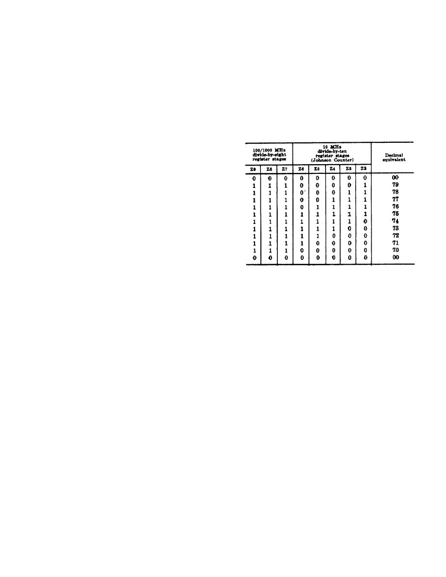
b. The 10 MHz divide-by-ten register stages Z2
switch. The divide-by-eight ripple-through counter Z7
through Z6 operate as a Johnson Counter (shift
through Z9 is a three stage nonsynchronous binary
register). The 100/1000 MHz divide-by eight ripple-
counter. Stages Z8 and Z7 are programmed by the B
through register stages Z7 through Z9 operate as a
and C inputs respectively from the 100/1000 MHz
standard three stage nonsynchronous binary counter.
thumbwheel switch. Stage Z9 (most significant bit) is
These register stages count down in accordance with
not programmed; the programmed input (reset) is
the following chart. It should be noted the chart lists the
connected permanently to logic 1 (+5 vdc). Because the
state of each register stage for 79 through 70. For 69
reset input to Z9 is permanently connected to a logic
through 00 the standard binary logic regression applies.
one, the lowest number that can be programmed into
the divide-by-eight register is decimal 4 or 100 binary.
c. The following describes the operation of the
divide-by-ten register (Johnson Counter). The count
e. If the count was not programmed by the control
pulses from 1A14A4 are applied to the divide-by-ten
logic in variable 1 frequency divider 1A14A4
register. It is assumed that register stages Z2 through
Z6 are reset (00000). The first negative-going count
transition sets register stage Z2 (00001). To set a flip-
2-103
|
|
Privacy Statement - Press Release - Copyright Information. - Contact Us |
