 |
|||
|
|
|||
|
Page Title:
Variable 2 Frequency Divider 1A14A5 Circuit Functioning |
|
||
| ||||||||||
|
|  TM 11-5820-695-35
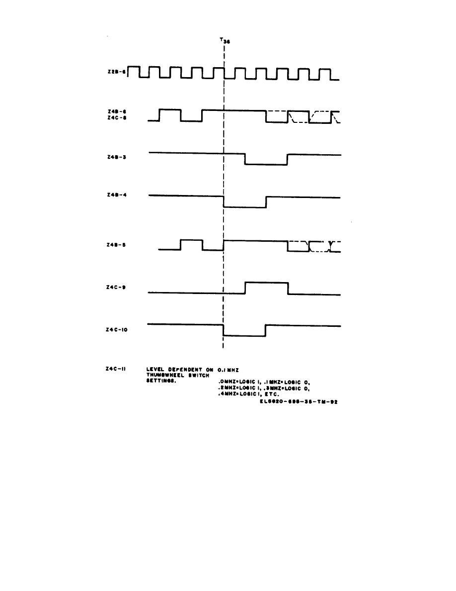
Figure 2-19. 1A14 timing diagram, 0.1 MHz thumbwheel switch.
Pressing the TEST pushbutton on the main chassis
circuit diagram for 2-102 each of
applies a +5 volt lamp test signal to pin P1-1, terminal
these circuits is shown in figure 6-24.
E19, and resistor R18 to the base of transistor in DS1,
lighting the lamp red.
printed wiring board A1 which provides the following
2-61. Variable 2 Frequency Divider 1A14A5 Circuit
circuits: 10 MHz divide-by-ten counter registers Z2
Functioning (fig. 641)
through Z6, 100/1000 MHz divide by-eight ripple through
counter registers Z7 through Z9, an output register Z10,
NOTE
and switch and control gates. The count signal from
Variable 2 frequency divider 1A14A5
variable 2 frequency divider 1A14A4 is applied to the
contains
integrated
circuits
divide-by-ten counter registers Z2 through Z6. The
designated Z1 through Z10 and Z12
output from the divide-by ten counter registers Z2
triggers
the
divide-by-eight
counter
register
through Z14. Integrated circuit types
MC932, 946, and 960 are used. A
2-102
|
|
Privacy Statement - Press Release - Copyright Information. - Contact Us |
