 |
|||
|
|
|||
|
Page Title:
Electrical Frequency Synthesizer 1A14 Circuit Functioning |
|
||
| ||||||||||
|
|  TM 11-5820-695-35
orderwire circuits. Transistor circuit Q2 is used as a
sidetone amplifier and is connected between the
transmit and receive elements of Handset H156/U. The
transmitted signal from Handset H156/U is applied to
the base of Q2 by pin R and capacitor C8. The output
of Q2 (emitter follower configuration) is applied to the
receive element of Handset H-156/U through resistor
R22 and pin S. Resistors R20 and R21 provide the
proper bias for transistor Q2. Dc power is supplied to
the microphone of Handset H-156/U through dropping
b. Indicator Lamps. Two power indicator lamps
resistor R18.
on electrical equipment chassis 1A14A10 indicate the
presence of the +28 volt and +6 volt power from power
2-56. Electrical Frequency Synthesizer 1A14 Circuit
supply 1A14A8.
Operational indicator lamps are
Functioning
provided on plug-in components 1A14A1-1A14A6. A
lighted (red) lamp indicates a failure in the associated
Electrical frequency synthesizer 1A14 provides an rf
plug-in components.
output frequency in the range of 284.275 MHz to
303.125 MHz. The 1A14 output is applied to transmitter
amplifier-frequency multiplier 1A11 in the T1054/GRC-
c. Integrated Circuit Z1. Integrated circuit Z1 (type
144 and to amplifier-frequency multiplier 2A10 in the R-
933) provides a diode distribution network for the +5 volt
1467/GRC-144.
Figure 5-45, electrical frequency
lamp test signal. Pressing TEST pushbutton S2 applies
synthesizer 1A14 interconnecting diagram, shows the
5 volts dc to this network which, in turn distributes it to
chassis mounted components and plug-in component
the individual operational indicator lamp bias circuits.
connections.
The circuit theory for the plug-in
components is given in paragraphs 2-57 through 2-64.
d. Relay Circuit.
Relay K1 is controlled by
All circuit theory and associated illustrations also apply
application of power to the crystal oven in standard rf
to electrical frequency synthesizer 2A14 in Receiver,
oscillator 1A14A7 Relay K1 is shown in the deenergized
Radio R1467/GRC-144.
position which indicates that the crystal oven has
reached its operating temperature.
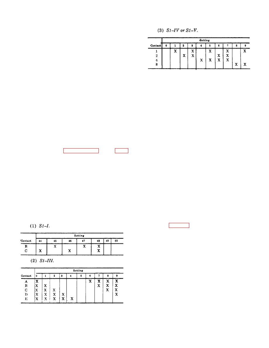
a. Thumbwheel Switches.
Four thumbwheel
switches: S1-I (S1-II dummy), S1-III, S1-IV, and S1-V
When the crystal oven is not at its operating
(fig. 5-45(1)) provide +6 vdc return (ground) connections
temperature, 28 volts de is applied to the relay coil from
to the switch gate inputs of variable frequency dividers
pins 4 and 6 of plug XA7. This energizes relay K1 and
and 1A14A5 in accordance with their settings; the
provides an open circuit at pins A3, B3, causing the
contact configurations for each thumbwheel .switch
SYNTH OVEN indicator on meter panel assembly
setting are indicated below. An X indicates the switch
1A15A8 to go out.
closed position which applied a +5 vdc return (ground)
line to the associated switch gated input.
2-57. Radio Frequency Oscillator 1A14A1 Circuit
Functioning (fig. 5-46)
a. Power (+28 volts dc) from power supply 1A14A8
is applied through pins 1 and 5 of connector P1 to
terminal E12 on board A3 and to the input of voltage
regulator VR1. This regulator produces 21 volts + 1
percent which is applied to radio frequency oscillator
(vco) Y1 through rf choke L13, to board A4 through rf
choke L4 and to board A2. RF feedthroughs FL1, FL2,
and FL3 filter rf currents which might adversely affect
the circuit operation.
b. The rf output frequency generated by the radio
frequency oscillator Y1 is determined by the vco bias
voltage produced in audio frequency phase error
detector 1A14A3 and applied through coaxial connector
P1-A3
and
terminal
El.
The
2-94 Change 3
|
|
Privacy Statement - Press Release - Copyright Information. - Contact Us |
