 |
|||
|
|
|||
|
Page Title:
Input signals at U4A and U11D are logic 0 (normal) or logic 1 (fault) |
|
||
| ||||||||||
|
|  TM 11-5820-695-35
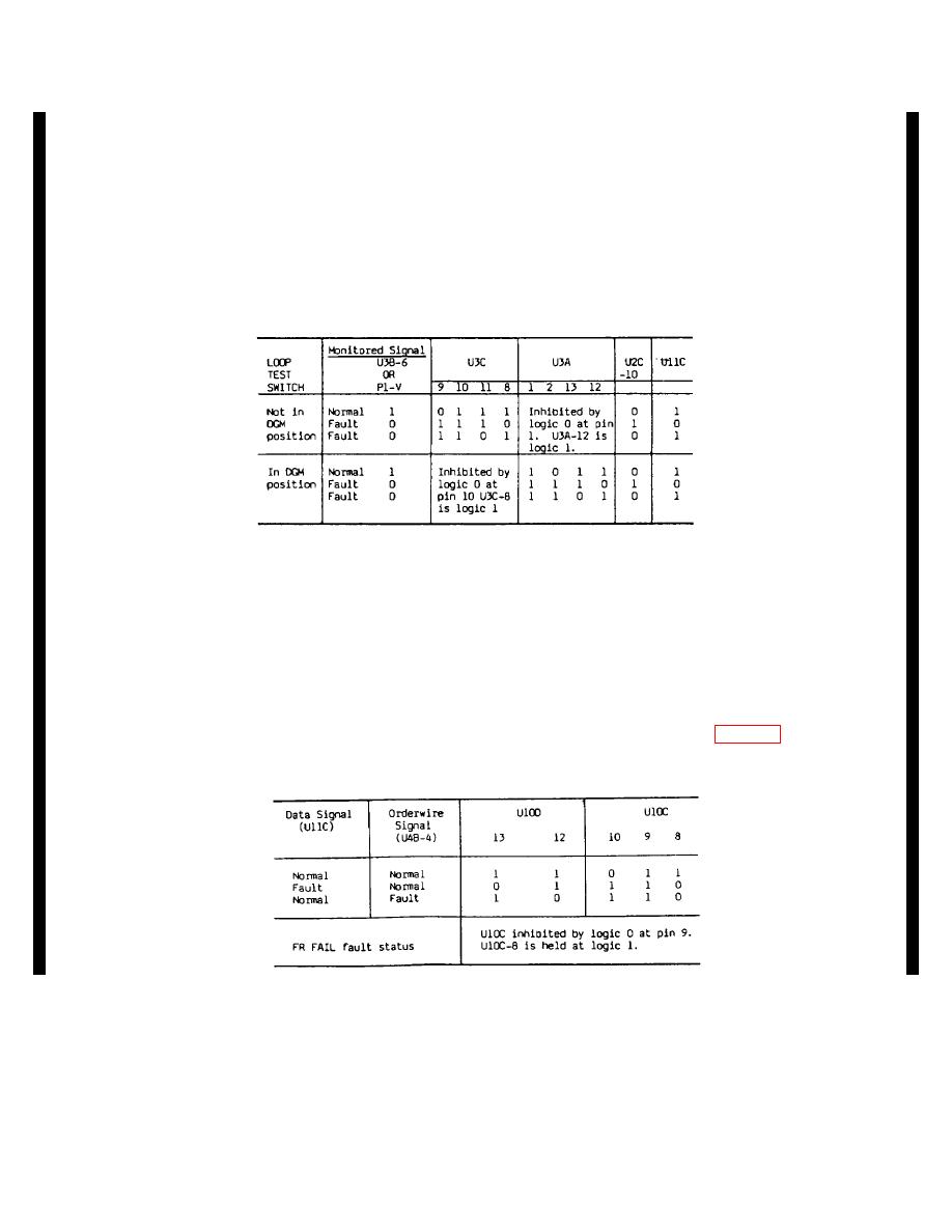
the monitored signal at U3C-9. The fault state is listed
(2) Input signals at U4A and U11D are logic 0 (normal)
twice. If FR FAIL (U3C-ll) is normal, U3C-8 is logic O
or logic 1 (fault). All FAIL signals including DSCRM
(fault) for monitored signal fault status. But if FR FAIL
FAIL at the input to U3B are logic 1 (normal) or logic 0
is logic 1 (fault), U3C is inhibited by logic 0 at pin 11 and
(fault) and the resulting output signal at U3B-6 for either
U3C-8 is logic 1 regardless of the logic state of the
logic state is indicated in the chart below in the
monitored signal (U3C-9). Operation of U3A is similar
MONITORED SIGNAL column. U3C monitors the
as indicated in the chart below. For U3A, logic 0 at pin
summary signal from U3B-6 and U3A monitors the DT
13 inhibits fault status indication at U3A-12 when EQPT
FAIL signal. U3C and U3A are each inhibited for one
FAIL signal is logic 1 (fault). The output signals at U3C-
position of the LOOP TEST switch as indicated in the
8 and U3A-12 are summarized by U2C and U11C.
chart. When U3C is not inhibited by the CLB signal
(U3C-10), the signal at U3C-8 shows the logic state of
held at logic 1 by a logic 0 at UlOC-9. The chart below
summarizes the logic action. When UlOC-8 is logic 1
(3) Input signals at U4B are normally logic 0
(normally), signal 1RFFL is logic 0. This signal is routed
and the signal at UlOD-12 is logic 1. If either input at
through P1-6 to meter panel 1A1548. Logic 0 causes
U4B fails, logic 0 is applied at UlOD-12. U4B monitors
RADIO TO CABLE MODEM indicator lA15A8DS2
orderwire signals; the output signal at U11C reflects the
(green) to light. At the same time, signal ORFFL is logic
status of data signals. These are the inputs to UOD and
1. This signal through P1-F holds indicator 1A15A80S4
the output at U1OD-ll is connected at U1OC-10O. This
(red) off. If the signal at UlOC-8 changes to logic O,
signal reflects the status of monitored data and
1RFFL is logic 1 (green lamp off) and ORFFL is logic 0
orderwire signals. The FR FAIL signal at U1OC-9 is an
(red lamp on). The output at UlOC-8 is also used in
inhibit signal. If FR FAIL is normal, the signal at UlOC-9
cable-to-radio monitor circuits (para 2-5 lb).
is logic and the signal at UlOC-8 can show the status of
the signal at U1OD-ll. If FR FAIL is logic 1, UlOC-8 is
Change 6 2-24.2
|
|
Privacy Statement - Press Release - Copyright Information. - Contact Us |
