 |
|||
|
|
|||
|
Page Title:
Digital Data Combiner 1A12 Radio-To-Cable Circuits Functional Block Diagram Description |
|
||
| ||||||||||
|
|  TM 11-5820-695-35
2-6.1 Digital Data Combiner 1A12 Radio-To-Cable
(1) The FR FAIL signal is applied directly at
Circuits Functional Block Diagram Description
U2A-1 and through inverter U6B at U6C-5, U7D-4, U3C-
11, UlOC-9 and to cable-to-radio monitor circuits (para
The functional relationships between radio-to-cable
2.5.1b). FR FAIL is normally logic 0 and U6B-4 is logic
plug-in components and J
chassis circuits of digital
1. This signal, twice inverted in U6C and U7C, applies
data combiner 1A12 are shown in figure 5-8.3. Each
logic 1 (open circuit) at relay K2 and K2 is deenergized
plug-in component is functionalized and the main signal
(normal). The relay contacts are open circuit and logic 1
paths (heavy lines) are shown in figure 5-8.3 as well as
(normal) is sent to the OCU. If FR FAIL changes to
control and alarm functions.
logic 1, the logic signals reverse, K2 is energized and
logic 0 (fault) signal is sent to the OCU. Signal 1
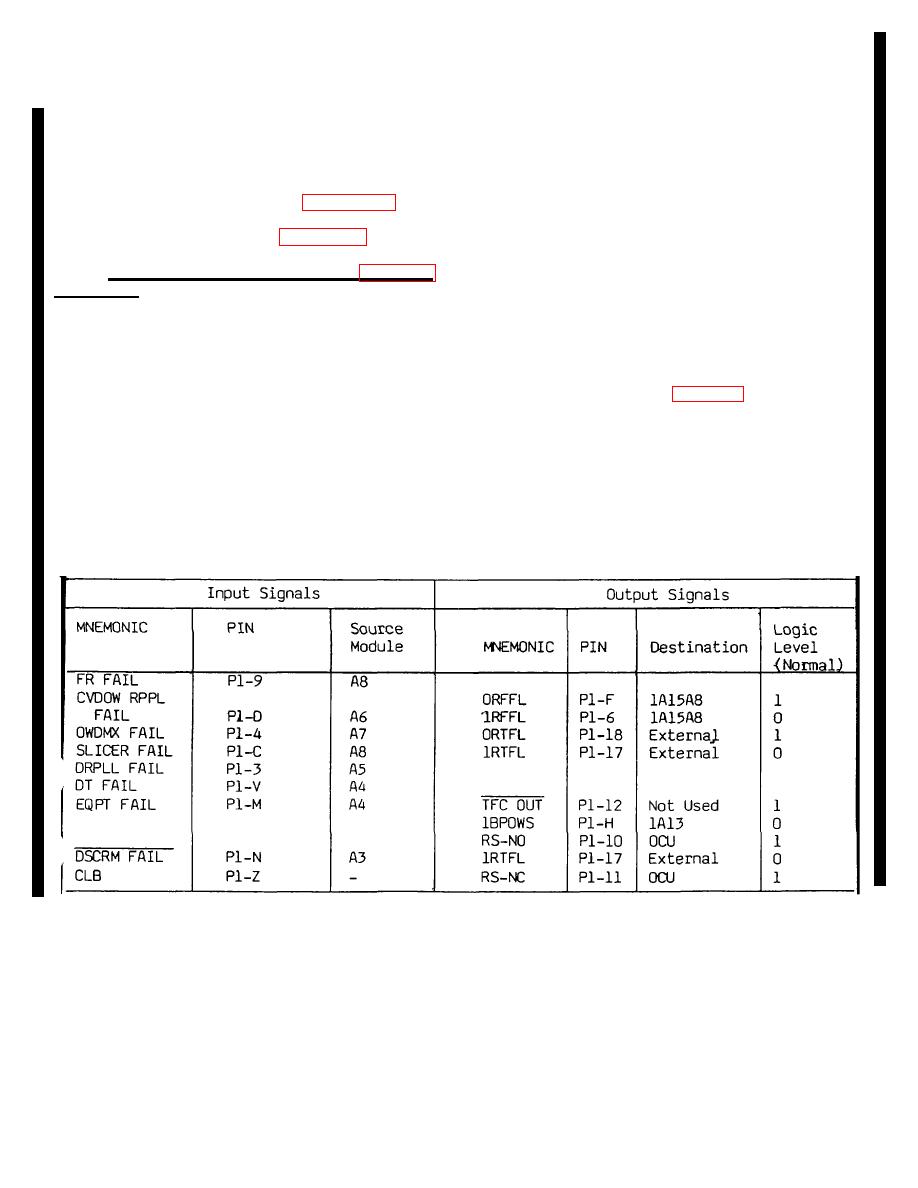
a. Combiner, Alarm-Status 1A12A2 (fig. 5-8.3
BPOWS at U7D-13 is normally logic A. This signal is
and 5-38.4). Combiner, alarm-status -11252 receives
used only in analog orderwire mode. It is connected
radio-to-cable status input signals as listed on the
through P1-H to AVOW switch 1A1252 at 52-1. The
following page. It processes these signals to generate
switch arm (52.2) is connected to OW SEL switch
output status signals that are routed to destinations
1A12S1 at S1-4 and the arm (S1-C2) is connected
indicated in the chart. The CLB signal is from LOOP
through P1-5 to route the signal to orderwire assembly
TEST switch 1A12S3; CLB is logic I when S3 is not in
lA13 at module 1A1343 (para 2-8e). The 1 BPOWS
DGM position and logic 0 when it is in DGM position. All
signal is connected-through this path only when S2
other input signals listed are logic 1 for normal status
(AVOW) is in the NORMAL position and S1 t(OW SEL)
and logic 0 for fault status. Normal logic states for --
is in the ANLG position. For any other combination of
output signals are listed in the chart below All input
positions of S1 and S2, the output at P1-H is open
signals listed are radio-to-cable monitor signals except
circuit. If the FR FAIL signal goes to fault status (logic
EQPT FAIL. This is a cable-to-radio signal (para 2.5. lb)
1), 1 BPOWS is also logic 1 and, in analog orderwire
and it is used here for an inhibit function.
mode, orderwire assembly 1A13 generates an alarm
signal that lights the CNTRL ALARM red indicator at
lA15A8.
Change 6 2-24.1
|
|
Privacy Statement - Press Release - Copyright Information. - Contact Us |
