 |
|||
|
|
|||
|
Page Title:
Digital Interface Buffer 1A12A4 |
|
||
| ||||||||||
|
|  TM 11-5820-695-35
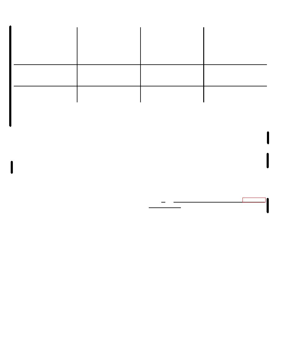
1A12A3
Connector
U11C-8
Randomizer
Status
5
6
Section
Scrambler
Normal
0
1
1
Fault
1
1
0
Descrambler
Normal
0
1
1
Fault
0
0
0
to alarm-status combiner 1A12A2 module. The outputs
provides a logic 1 input at least once every 150 msec,
of failure monitors U9B and U5A are applied at U14D
the monostable is maintained in the set state (Q at logic
pins 12 and 13 so that a RCVOD DATA or DSCRM
1, Q at logic 0). If the monitored signal fails, the
DATA failure will time out U5A or U9B respectively and
monostable times out after 150 msec and is reset.
change the logic condition at the input to U14C, turning
When all randomizer circuits are operating normally the
on CR1 (fault) as described above. The logic 0 at
levels at U14C-9 and U14C-10 are a logic 1 and the
U14D-11 is the DSCRM FAIL signal to alarm status
SCRM FAIL (pin 5) and the DSCRM FAIL (pin 6) levels
combiner 1A12A2 module. Failure monitor U5B is used
are as give below. The output signal at U14C-8 is a
to monitor the INHB/OPR jumper P2 positions. When
logic 0 when randomizer circuits are operating normally.
jumper P2 is in the OPR position, operation of U5B is
Pullup resistor R14 provides a logic 1 at U11C-10. With
identical to that of U5A, except that the output at U5B-5
a logic 1 and logic 0 at U11C-9 and U11C-10
is a logic 1 and the status indicator CR2 is off. When
respectively, the signal at U11C-8 is a logic 1 and the
jumper P2 is in the INHB position a ground is applied to
status indicator CR1 is off (normal). With a SCRAM
U5B-9 and the failure monitor times out (Q goes to a
DATA or DSCRM DATA failure the logic inputs to U14C
logic 0) turning on status indicator CR2, indicating that
change. The logic level at U14C-8 is changed to a logic
randomizer operation is inhibited.
1 and U11C-8 is changed to a logic 0; these conditions
turn on CR1 (fault). If the SCRM DATA signal (from
d.
Digital Interface Buffer 1A12A4 (fig. 5-8.2
U4B through U12A) is active, U9A is held in the set
state and the signal at U14C-9 is logic 1. If the SCRM
and 5-38.6). Digital interface buffer 1A12A4 is the
DATA fails, U9A times out and resets (Q at logic 0, Q at
interface for data signals to and from the DGM and it
logic 1) and applies a logic 0 at U14C-9 and logic 1 at
combines the CVDOW signal from module A1
U9A-4. The logic 1 at U9A-4 is the SCRM FAIL signal
Change 6 2-16.9
|
|
Privacy Statement - Press Release - Copyright Information. - Contact Us |
