 |
|||
|
|
|||
|
Page Title:
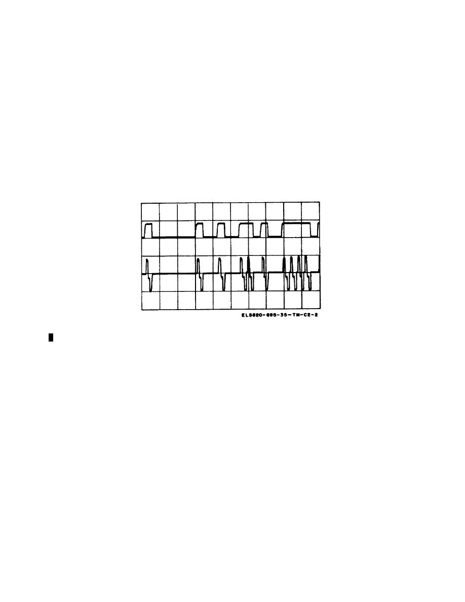
Figure 2-2.1. Cable digital regenerator 1A12A13, pcm signal waveform, asynchronous mode. |
|
||
| ||||||||||
|
|  TM 11-5820-695-35
(1CSPCM), It can be seen that it occurs at the positive
going or leading edge of a data logic one. Generation of
(2) Input signal 1T4608 (4608 kHz cable-to-radio
the reset pulse for the phase comparator is discussed in
clock) is divided by two flip-flop A7A. The logic zero
the following paragraph.
output of A7A is connected to
Figure 2-2.1. Cable digital regenerator 1A12A13, pcm signal waveform, asynchronous mode.
Change 2 2-12.2
|
|
Privacy Statement - Press Release - Copyright Information. - Contact Us |
