 |
|||
|
|
|||
|
Page Title:
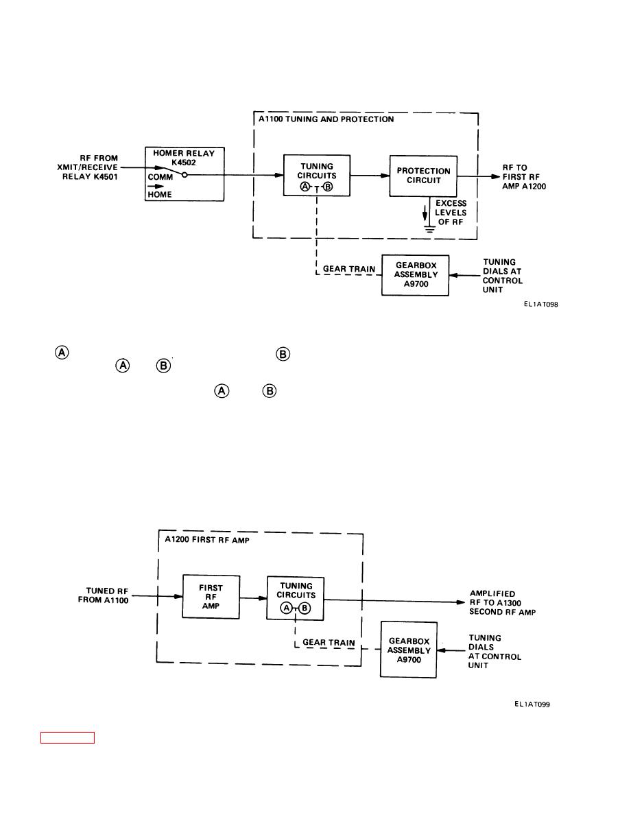
ANTENNA TUNING AND PROTECTION MODULE A1100. |
|
||
| ||||||||||
|
|  TM 11-5820-670-30
1-22. ANTENNA TUNING AND PROTECTION MODULE A1100.
to the A1100 tuning circuits which consist of tuned tank circuits. The tuning circuits consist of an
band, 30 MHz through 52.95 MHz, and a
band, 53 MHz through 75.95 MHz. The gear train
selects band
or
, depending on the setting of tuning dials at the control unit. The resonant
frequencies of the tank circuits are varied by rotating the tuning dials, which alter the inductance and
change the overall LC ratio in the
and
frequency range.
The bandwidths of the resonant tank circuits allow passage of signals of the selected frequency while
unwanted frequencies are rejected.
The protection circuit has a neon lamp which shunts excess rf signal strength to ground. From the
protection circuit, rf signals are applied to tuning circuits in the first rf amplifier.
1-23. FIRST RF AMPLIFIER MODULE A1200.
Rf signals are amplified by the first rf amplifier, which consists of vacuum tube V1201. The amplified
signals are then fed to tuning circuits which function similarly to those described in the previous
1-22
|
|
Privacy Statement - Press Release - Copyright Information. - Contact Us |
