 |
|||
|
|
|||
|
|
|||
| ||||||||||
|
|  TM 11-5820-670-12
INSTALLATION INSTRUCTIONS.
3-4.
The procedures in this paragraph provide the instructions for installing the radio set components into
the aircraft as received from the AVIM unit. All electrical connections to the components of the radio
set are made through the communications wiring harness which is aircraft installed. After installation
of any component, insure that receiver-transmitter squelch adjustment and a complete operational
check is performed.
Electronic Equipment Tool Kit TK-101/G is needed for all procedures. Tools will not be listed unless
they are not contained in the kit.
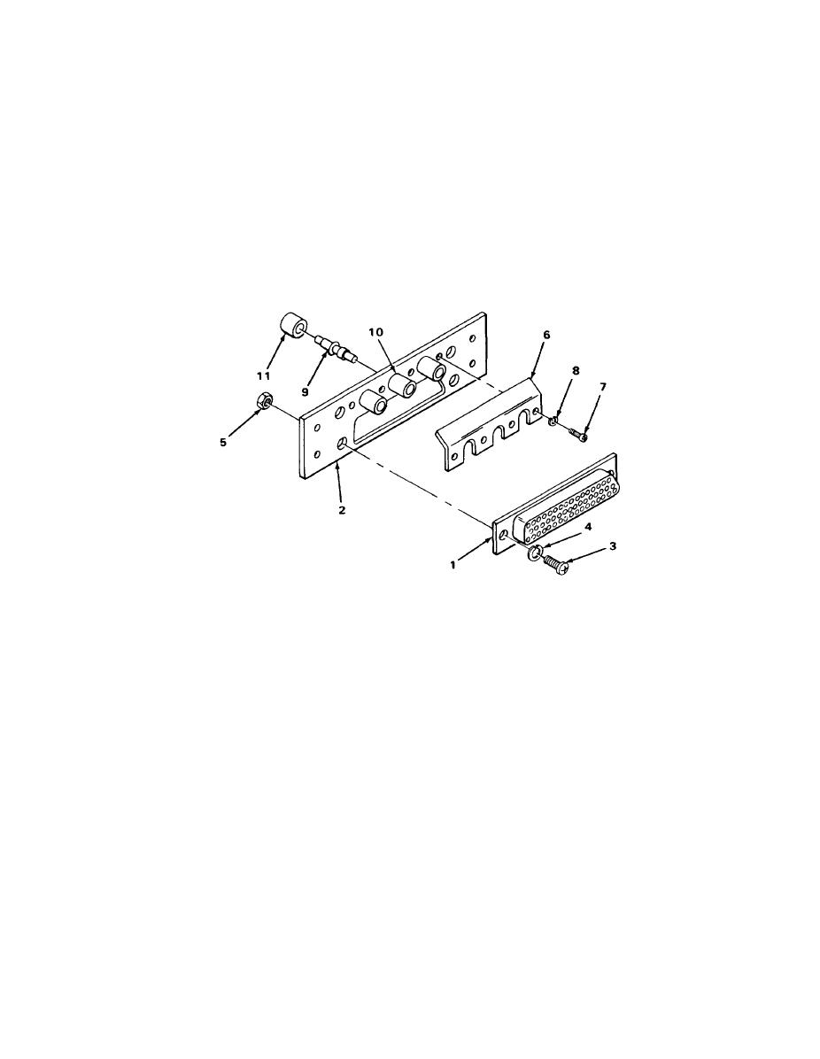
ASSEMBLY OF CONNECTOR PLATE SM-B-620336
EL7RM031
NOTE
Front side of mounting plate is indicated by longer coaxial contact mounts and beveled
guide-pin receptacle holes.
Position multiple-pin connector (1) onto front side of mounting plate (2).
1.
NOTE
Multiple-pin connector will seem loose when secured; this free play is necessary for
alinement reasons.
Secure multiple-pin connector (1) to mounting plate (2) with two screws (3), Iockwashers
2.
(4), and nuts (5).
Secure contact guard (6) to mounting plate (2) with four screws (7) and Iockwashers (8).
3.
Insert three coaxial contacts (9) into coaxial contact mounts (10) from rear. Coaxial cable
4.
sleeves (11) slide over coaxial cable jacket and solder to contact later.
3-3
|
|
Privacy Statement - Press Release - Copyright Information. - Contact Us |
