 |
|||
|
|
|||
|
Page Title:
Section IV. OPERATOR'S MAINTENANCE INSTRUCTIONS |
|
||
| ||||||||||
|
|  TM 11-5820-554-12
set to 14.296 MHz and the EMISSION switch on the
2/2A tuning dial. The VFO switch may then be
KWM-2/2A set to TUNE, the transmit circuits may
changed to REC 2-XMIT 2 position, and the Collins
be peaked and the pa loaded. The EMISSION switch
312B-5 dial adjusted to another selected frequency
is then set back to the desired sideband or CW, and
within the same band. Transceiver operation may
the Collins KWM-2/2A dial tuned to a desired
then be changed instantly from one frequency to the
receiving frequency between 14.3 and 14.350 MHz
other by operating the VFO switch on the Collins
312B-5 back and forth between the two positions
b. With the VFO selector switch in the REC 1-
marked REC 1-XMIT 1 and REC 2-XMIT 2. This
XMIT 1 position, both the receiver and transmitter
action permits presetting to a net frequency and a net
frequencies are the same and are controlled by the vfo
QSY frequency, and the instant selection of either
in the transceiver.
during net operation. Frequency separation limits
c. With the VFO selector switch in the REC 2-
listed in table 10-3 should not be exceeded by any
XMIT 2 position, both the receiver and transmitter
great extent. If they are exceeded, the result is
frequencies are the same and are controlled by the vfo
decreased receiver sensitivity or transmitter pa grid
in the Collins 312B-5. The vfo dial in the Collins
drive (or both) due to the selectivity of the transceiver
312B-5 can be calibrated in this position using the
RF tuned circuits. The best compromise for this tuned
crystal calibrator signal and zero set knob as outlined
circuit attenuation effect is to tune and load the
in paragraphs 3-9 through 3-13. With the Collins
Collins KWM-2/2A at a frequency midway between
312B-5 VFO switch set in REC 1-XMIT 1 position,
the two desired frequencies and then set the Collins
the Collins KWM-2/2A may be tuned and loaded to
312B-2 and Collins KWM-2/2A dials to the required
one selected frequency within the legal amateur band
frequencies.
using the Collins KWM-
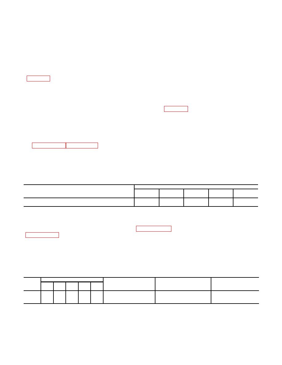
Table 10-3. Collins KWM-2/2A and Collins 312B-5 Approximate Vfo Frequency Separation Limits
Band (M Hz)
3.4-4
7-7.4
14-14.4
21-21.6
28-30
Approximate limit of separation between Collins 312B-5 and Collins
KWM-2/2A dials.
15 kHz
30 kHz
50 kHz
75 kHz
100 kHz
Section IV. OPERATOR'S MAINTENANCE INSTRUCTIONS
10-10. General
Operator's maintenance instructions are covered in paragraph 3-19 through 3-22.
Cleaning is covered in
10-11. Operator's Preventive Maintenance Checks and Services Chart for Controls, Radio Set
C-6118/FRC-93 and C-75151/FRC-93
B-Before
A-After
M-Monthly
D-During
W-Weekly
Interval
Item
B
D
A
W
M
Item to be inspected
Procedure
Equipment is not
No.
ready/available if:
Equipment performance
Check operation of VFO with
Frequency fails to track or
transmitter on dummy load
lacks stability once tuned
using frequency counter.
to fixed frequency.
Change 6
10-9
|
|
Privacy Statement - Press Release - Copyright Information. - Contact Us |
