 |
|||
|
|
|||
|
|
|||
| ||||||||||
|
|  TM 11-5820-554-12
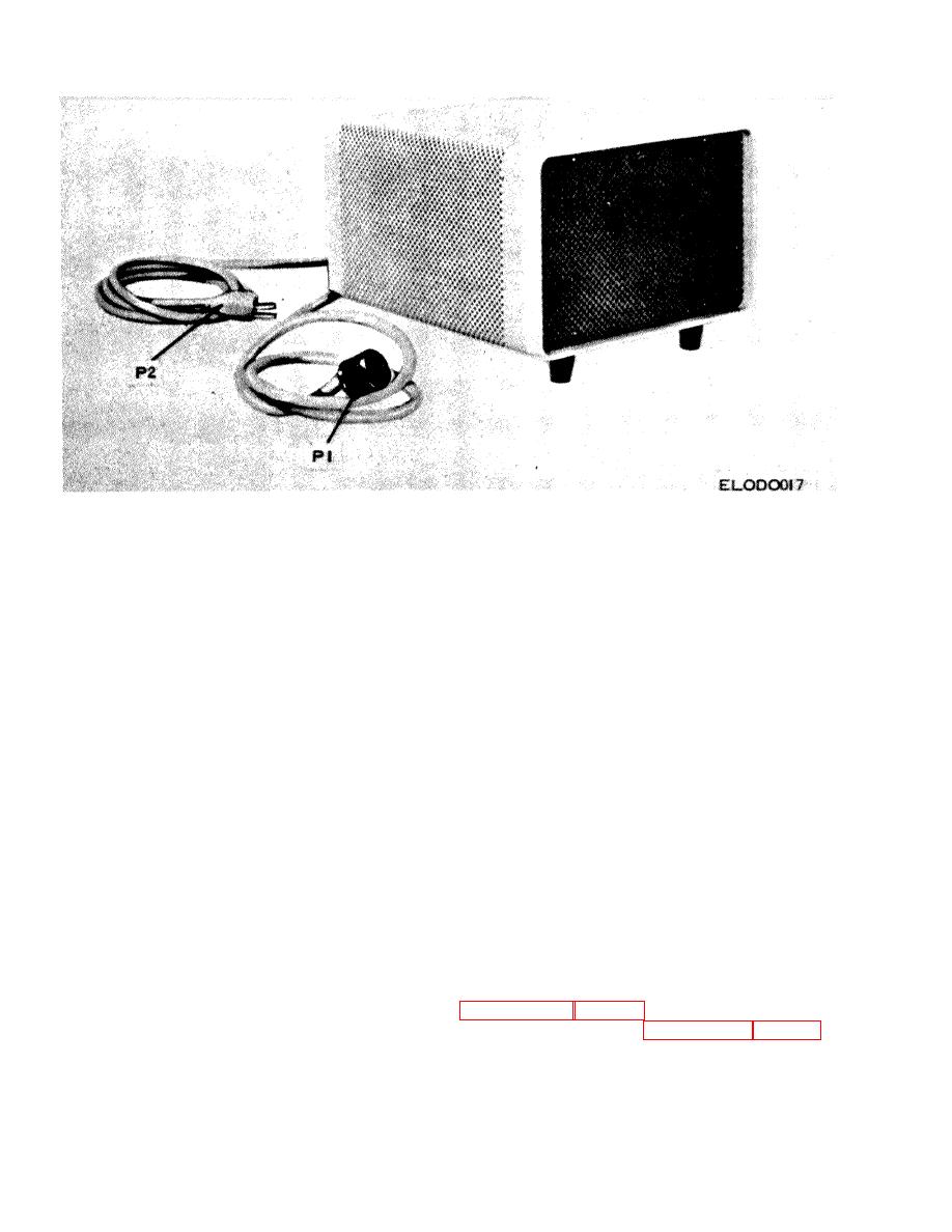
Figure 7-6. Power Supply PP-4151/FRC -93 S. location of power plugs P1 and P2.
(5) After a 2-minute warm-up period, the no
7-10. Installation
signal pa plate current, as monitored on the meter,
CAUTION
should be approximately 40 ma. If it is not 40 ma,
Possible damage to associated equipment
adjust BIAS ADJUST potentiometer R9 at the rear of
can result if the keyway of power plug P1 is
the PP-4151/FRC-93 until a 40-ma reading is obtained.
not aligned with the keyway of its
associated mating connector.
Always
NOTE
disconnect a.c. power plug P2 when joining
When using a line frequency higher than
P1 with its respective mating connector.
60 Hz, remove capacitor C1. Always
Always check for keyway alignment before
make sure adequate ventilation is provided
applying power, and be sure power
for the heat generating components of the
primaries
are
correctly
equipment.
connected for the line voltage to be used.
7-11. Operation
a. Plug connector P1 into its mating connector.
Operation of the PP 4151/FRC-93 is controlled
b. Plug line connector P2 into an a.c. outlet. If the
completely by switches and relays in the associated
a.c. outlet is not fitted with a mating connector, use the
equipment. The only adjustment provided in the PP
adapter furnished, and ground the green wire.
4151/FRC-93 is the -55- to -80-volt d.c. variable bias
c. Turn on the associated equipment and adjust
supply. This is a screwdriver adjustment accessible at
BIAS ADJUST potentiometer R9 (accessible at the rear
the rear of the unit. The bias adjustment will depend on
of the PP -93 4151/FRW93 without the cover removed)
the type of equipment used with the PP-4151/FRC-93.
to the desired bias level. The PP -4151/FRC-93 is now
ready for use. When using the Collins KWM-2/2A,
7-12. Operator's and Organizational
proceed as follows:
Maintenance Instructions
(1) Set the MIC GAIN control fully
Operator's maintenance instructions are covered in
counterclockwise.
(2) Set the EMISSION switch to LOCK.
instructions are covered in paragraph 7-28 and 7-29.
(3) Set the meter switch to PA PLATE.
(4) Set the OFF-ON-NB-CAL switch to ON.
7-6
|
|
Privacy Statement - Press Release - Copyright Information. - Contact Us |
