 |
|||
|
|
|||
|
|
|||
| ||||||||||
|
|  TM 11-5820-509-35
(5) Measure the output voltage at connector
Place the teat fixture POWER ON-OFF switch to OFF
and install the module in the test fixture.
J3-1 and set potentiometer R6 of the test set to obtain-
35 1.0 volts dc.
(8) Return the test fixture POWER ON-OFF
switch to ON and permit the module and the test
(6) Place the AVC ON-OFF switch of the test
fixture to ON and measure the output voltage at
equipment to stabilize for at least 5 minutes before
performing the remaining procedures.
connector J3-4. Set potentiometer R8 on the test fixture
to obtain-2.2 volts dc.
NOTE
(7) After
performing
the
mechanical
If
the
mechanical
alignment
alignment procedures of step c, replace the bottom
procedure was performed in (7)
cover on the CV-1377A/PRC-47, attach the indexing
above, proceed directly to step d and
fixture to the drive coupling end of the module with the
perform the remaining procedures in
three knurled thumbscrews.
the order listed.
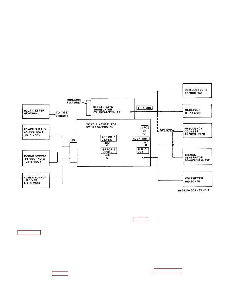
Figure 6-13. Signal Data Translator CV-1377A/PRC - 47 (A8A3), Performance Tests, Initial Test Equipment
Connections.
from the bottom of the coil form (second ring on plug
c. Mechanical Alignment.
This procedure is
gage (fig. 6-1)).
performed with the module disconnected from the test
fixture. The bottom cover must be loosened and
(3) Set the slug of coil L4 to a depth of
removed to provide access to the inductor slugs. Refer
5/32inch from the bottom of the coil form (first ring on
to figures 3-41, 3-96 through 3-98, and 3-105 for the
plug gage), and set L5 slug to a depth of 1/4-inch from
location of adjustments referred to in these procedures.
the bottom of the coil form (third ring on the plug gage).
Set the slug of coil L145 to a depth of 9/32 inch (fourth
(1) Using multimeter ME-26A/U, check the
ring on the plug gage).
internal resistance between connector P3-3 and ground,
and between P3-4 and ground; each reading shall be
(4) Remove the 0.041" overtravel tool from
100 ohms 10 %
the slug rack, install the bottom cover of the module,
and install the module in the test fixture.
(2) Attach the 0.041" overtravel tool to the
slug rack. With the control on the indexing fixture set
NOTE
for 000 (slugs fully inserted in their respective coils),
Return to paragraph 6-12 b (7) and
adjust L1, L2, and L3 (fig. 3-96) to a depth of 7/32-inch
6-19
|
|
Privacy Statement - Press Release - Copyright Information. - Contact Us |
