 |
|||
|
|
|||
|
|
|||
| ||||||||||
|
|  TM 1 1-5820-509-35
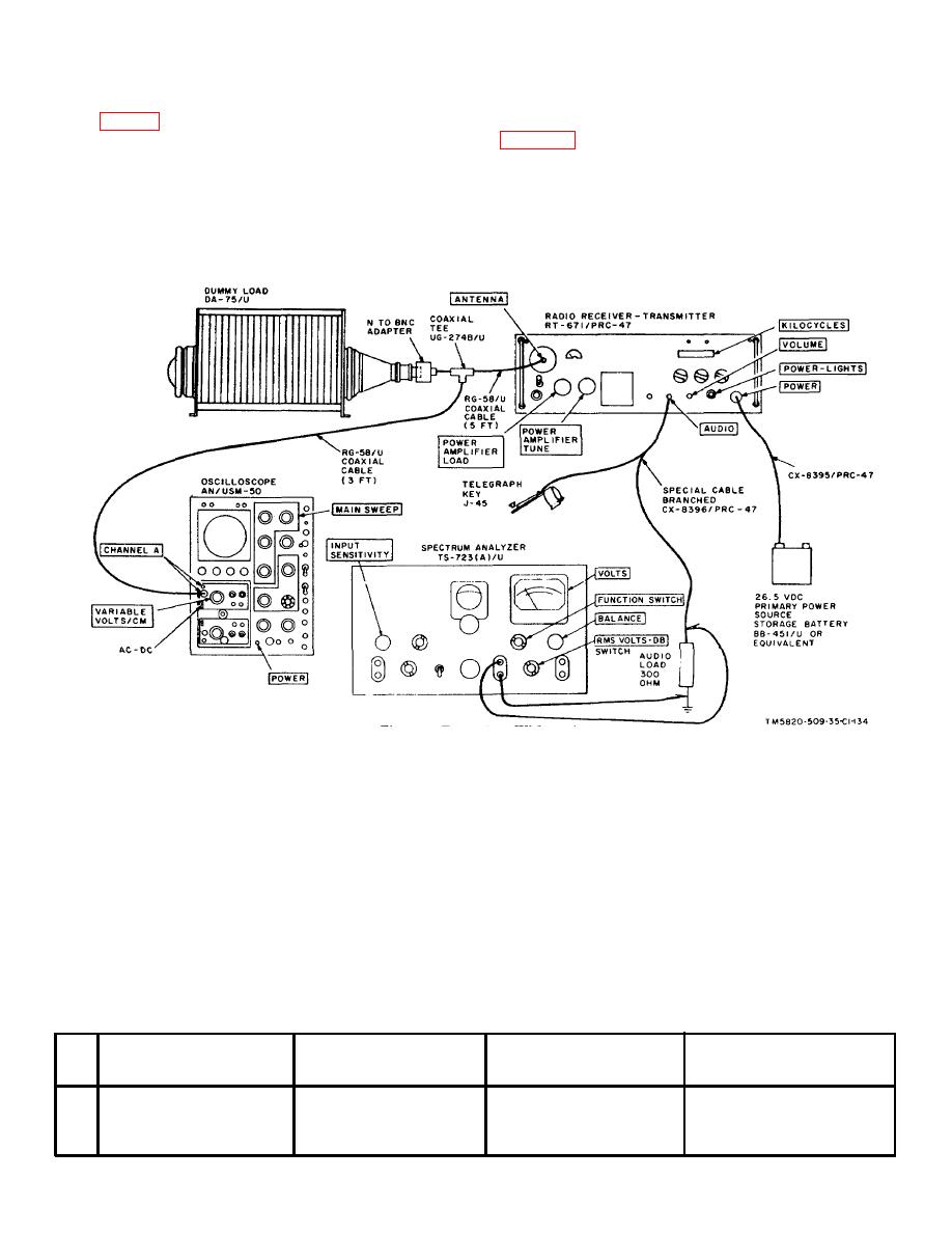
4-18. Transmitter CW Operation Test
(1) Connect the test equipment to Radio
Receiver-Transmitter RT-671/PRC-47 as shown in
a. Test Equipment and Material.
(2) Connect the primary power source to the
(1) Oscilloscope AN/USM-50.
receiver-transmitter.
(2) Dummy Load DA-75/U.
(3) Turn on the test equipment and place the
(3) Telegraph Key J-45.
POWER-LIGHTS switch on RT-671/PRC-47 to POWER
(4) Primary power source:
26.5-volt, dc,
ON. Permit the equipment to stabilize at least 5
amperes approx.
minutes before beginning the procedures shown in the
b. Test Conditions and Equipment Connections.
chart below.
Figure 4-7. Transmitter CW Operation
and Sidetone Test, Equipment Setup
CAUTION
Before
making
the
following
c. Procedure
measurements, resonate the POWER
(1) On
RT-671/PRC-47,
set
the
AMPLIFIER TUNE and POWER
KILOCYCLES indicator to 2000; place the CW-
AMPLIFIER LOAD controls on the
FSK/VOICE switch to VOICE, the XMTR PWR switch to
front of the receiver-transmitter. for
LO, and the OPR-TUNE switch to OPR.
maximum deflection on the XMTR
(2) Place the turns-counters of POWER
OUTPUT meter. Use the OPR-TUNE
AMPLIFIER TUNE and POWER AMPLIFIER LOAD
switch to control power amplifier
controls to the settings recommended on the LOAD-
plate power.
Do not permit the
TUNE chart on the front of the receiver-transmitter.
power amplifier to operate more than
a few seconds in the unloaded or off-
resonant
condition,
serious
equipment damage can result.
Test
Radio
equipment
control
Test
Performance
Step
settings
settings
procedures
standards
1
Adjust oscilloscope sweep to
Verify that OPR-TUNE switch
Key the transmitter with the
Transmitter must key at all oper-
provide a keying envelope
is at OPR; then place the CW-
telegraph key at speeds from
ating speeds up to 25 wpm with-
display at each keying speed.
FSK/VOICE switch to CW-
5- to 25-wpm. Observe the
out missing character or elements.
FSK.
keying envelope for dis-
continuities.
Change 1 4-17
|
|
Privacy Statement - Press Release - Copyright Information. - Contact Us |
