 |
|||
|
|
|||
|
Page Title:
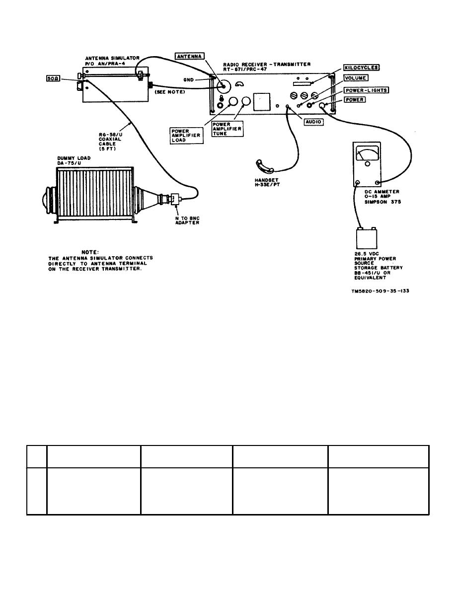
Figure 4-6. Transmitter Power Input Test, Equipment Setup. |
|
||
| ||||||||||
|
|  TM 11-5820-509-35
Figure 4-6. Transmitter Power Input Test, Equipment Setup.
c. Procedure.
CAUTION
Before
making
the
following
(1) Set the selector switch on the antenna
measurements, resonate the POWER
simulator to the 2000 kHz position.
AMPLIFIER TUNE and POWER
(2) On
RT
671/PRC
47,
set
the
AMPLIFIER LOAD controls on the
KILOCYCLES indicator to 2000; set CW-FSK/VOICE
front of the receiver-transmitter for
switch to VOICE, the XMTR PWR switch to LO, and the
maximum deflection of the XMTR
OPR-TUNE switch to OAR.
OUTPUT meter. Use the OPR-TUNE
(3) Place the turns-counters of POWER
switch to control power amplifier
AMPLIFIER TUNE and POWER AMPLIFIER LOAD
plate power.
Do not permit the
controls to the settings recommended on the LOAD-
TUNE chart on the front of the receiver-transmitter.
power amplifier to operate for more
than a few seconds in the unloaded
or off-resonant condition, serious
equipment damage can result.
Test
Radio
equipment
control
Test
Performance
Step
settings
settings
procedures
standards
1
n/a
Place XMTR PWR switch
Return OPR-TUNE switch
Dc ammeter reads not more
to HI and resonate power
to OPR and close handset
than 12.5 amperes.
amplifier output circuit to
push-to-talk
switch.
Maximum output with
Speak normally into the
OPR-TUNE switch in
microphone. Observe dc
TUNE position.
ammeter reading.
4-16
|
|
Privacy Statement - Press Release - Copyright Information. - Contact Us |
