 |
|||
|
|
|||
|
Page Title:
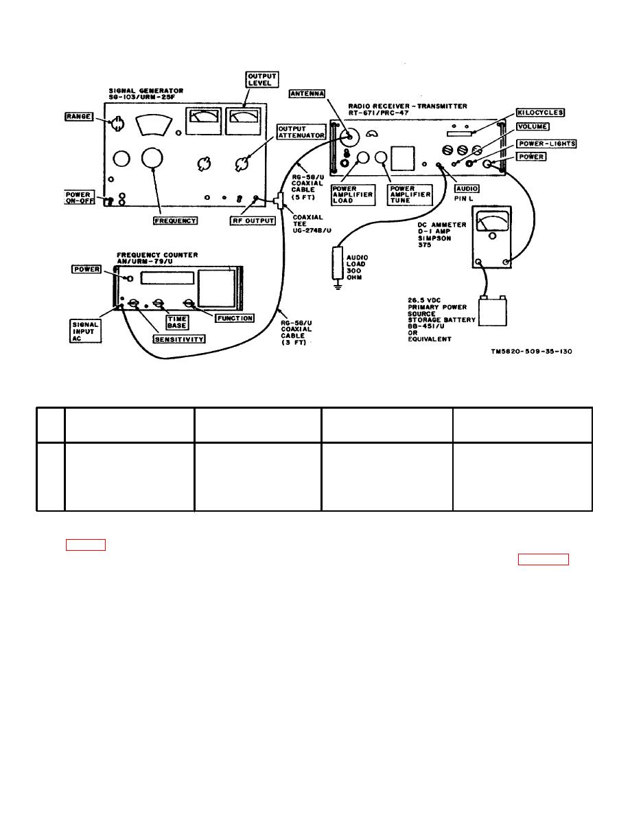
Figure 4-3. Receiver Power Input Requirements, Equipment Setup. |
|
||
| ||||||||||
|
|  TM 11-5820-509-35
Figure 4-3. Receiver Power Input Requirements, Equipment Setup.
c. Procedure.
Test
Radio
equipment
control
Test
Performance
Step
settings
settings
procedures
standards
1
Adjust signal generator to
Adjust frequency control
Read dc ammeter.
Dc ammeter reads not more
2226 kHz; set output level
knobs to 2225 on
than 0.875 amperes.
to 1000 microvolts.
KILOCYCLES indicator;
CW-FSK/VOICE to
VOICE; OPR-TUNE to
OPR.
4-14. Transmitter Power Output Test
(1) Connect the test equipment to Radio Receiver-
Transmitter RT-671/PRC-47 as shown in figure 4-4.
a. Test Equipment and Material.
(2) Connect the primary power source to the receiver-
(1) Antenna simulator (p/o Cable Assembly
Set AN/PRA-4)
(2) Dummy Load DA-75/13
(3) Turn on the test equipment and place the POWER-
LIGHTS switch on RT-671/PRC-47 to POWER ON.
(3) Multimeter ME-26A/U
Permit the equipment to stabilize at least 5 minutes
(4) Primary power source: 26.5-volt, dc, 11
before beginning the procedures shown in the chart
amperes approx.
below.
b. Test Conditions and Equipment Connections.
4-9
|
|
Privacy Statement - Press Release - Copyright Information. - Contact Us |
