 |
|||
|
|
|||
|
Page Title:
Power Input Requirements, Receive Mode |
|
||
| ||||||||||
|
|  TM 11-5820-509-35
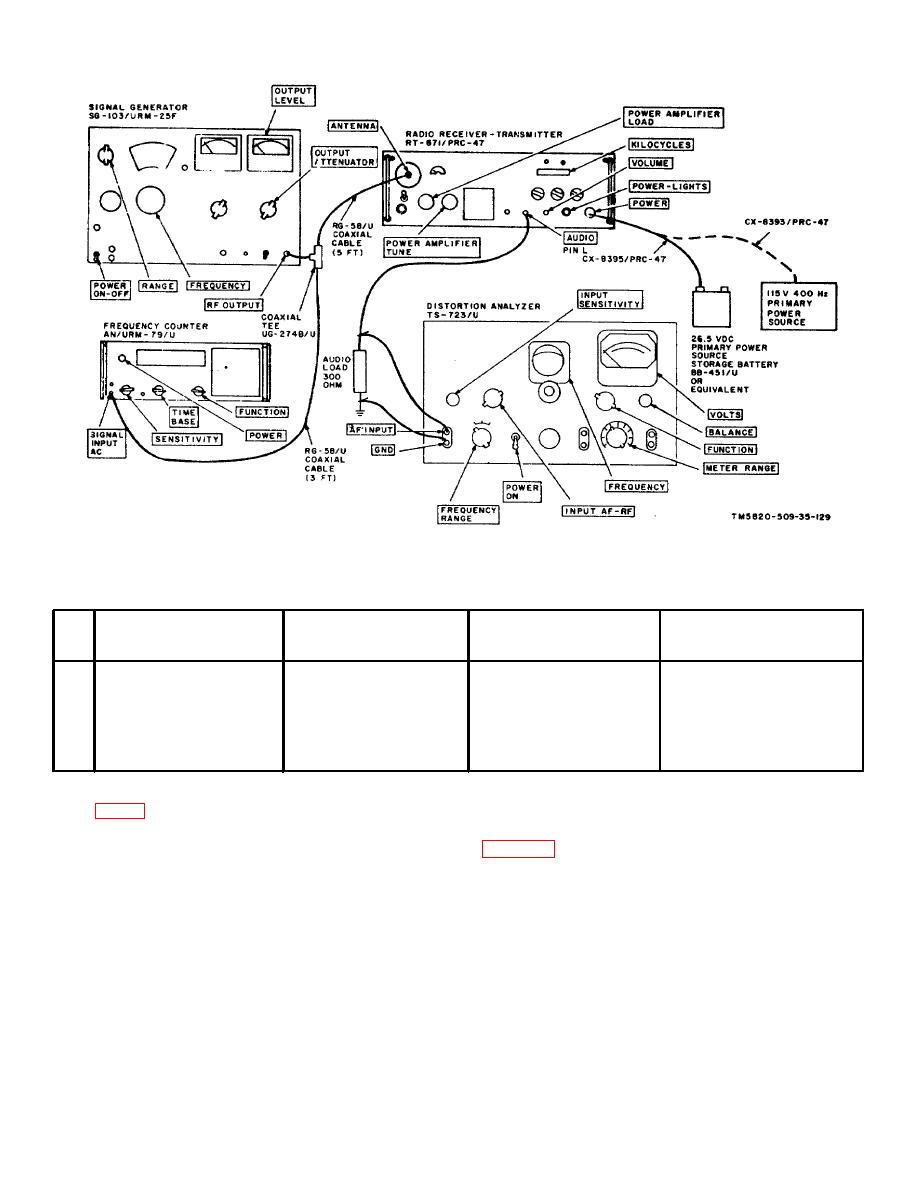
Figure 4-2. Receiver Audio Output Distortion Test, Equipment Setup.
c. Procedure.
Test
Radio
equipment
control
Test
Performance
Step
settings
settings
procedures
standards
1
Adjust signal generator to
Adjust frequency control
Set VOLUME control to
Audio output distortion less
2225.3 kHz: set output
knobs to 2225 on
obtain 12.9 volts across
than 15%.
level to 1000 microvolts
KILOCYCLES indicator:
the 300-ohm audio load
CW-FSK/VOICE to
(500 milliwatts); read
VOICE: OPR-TUNE to distortion.
OPR.
4-13. Power Input Requirements, Receive Mode
(1) Connect the test equipment to Radio
Receiver-Transmitter RT-671/PRC-47 as shown in
a. Test Equipment and Material.
(2) Connect the primary power source to the
(1) Signal Generator SG-103/URM-25F
receiver-transmitter.
(2) Frequency Counter AN /URM 79/U
(3) Turn on the test equipment and place the
POWER-LIGHTS switch on RT-671/PRC-47 to POWER
(3) Dc ammeter, 0 to 1 ampere. Simpson
ON. Permit the equipment to stabilize at least 5
375, or equal.
minutes before beginning the procedures shown in the
(4) Audio load, 300-ohm, I watt composition
chart below.
resistor.
b. Test Conditions and Equipment Connections.
(5) Primary power source: 26.5 volt, dc. 11
amperes approx .
4-8
|
|
Privacy Statement - Press Release - Copyright Information. - Contact Us |
