 |
|||
|
|
|||
|
|
|||
| ||||||||||
|
|  TM 11-5820-509-35
4-6. Receiver Sensitivity Tests
(6) Primary power source: 115-volt, 400-Hz,
single-phase, 3 amps.
26.5-volt, dc, 11 amperes
NOTE
approx.
This test must be performed in a
b. Test Conditions and Equipment Connections.
screen-room similar to Electro-
(1) Connect the test equipment to Radio
Magnetic Shielding Enclosure MX-
Receiver-Transmitter RT-671/PRC-47 as shown in
1766/G or equal.
(2) Connect the 115-volt primary power
a. Test Equipment and Material.
source to the receiver-transmitter.
(1) Signal Generator SC-103/URM-25F.
(3) Turn on the test equipment and place the
POWER-LIGHTS switch of RT-671/PRC-47 to POWER
(2) Frequency Counter AN/URM-79/U.
ON. Permit the equipment to stabilize for at least 6
(3) Spectrum Analyzer TS-723A/U.
minutes before beginning the procedures shown in the
(4) Audio load, 300-ohm, 1-watt composition
chart below.
resistor.
(5) Coaxial tee, UG-274B/U.
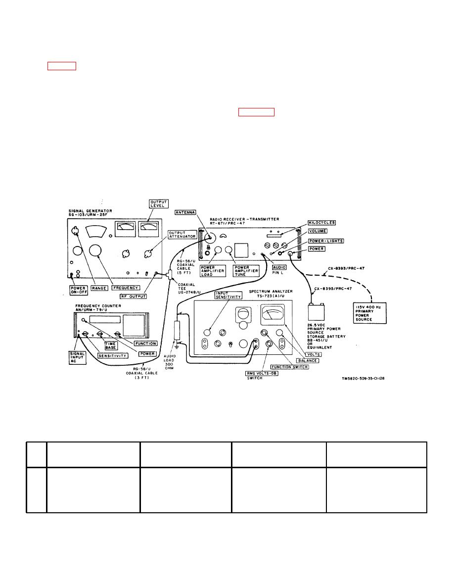
Figure 4-1. Receiver Sensitivity, AVC Selectivity, IF. Rejection,
Image Rejection, and Volume Control Tests, Equipment Setup.
c. Procedure After each adjustment of the
output frequency to the newly selected transmitter
frequency control knobs on the front panel of the
operating frequency, plus 1 kHz, and reset the output
receiver-transmitter, readjust the signal generator
level to the required value.
Test
Radio
equipment
control
Test
Performance
Step
settings
settings
procedures
standards
1
Adjustsignalgeneratorto2226kHz;
Adjustfrequencycontrolknobs
a.
Readaudiooutputvoltage
a.
Minimum accept ablevoltageof1.9voltsrms.
kHz;setoutputlevelto2.0
to2225onKILOCYCLES
across300-ohmaudioload.
of3.9voltsrms
microvolts.
indicatorCW-FSK/VOICE to
b.
Disconnectsignal generator
b.
Maximumacceptablevoltage1.25voltsrms.
VOICE;OPR-TUNEto
fromANTENNAterminal
1.25voltsrms.
Tomaximumclockwisestop.
Across300-ohmaudioload.
Change 1 4-2
|
|
Privacy Statement - Press Release - Copyright Information. - Contact Us |
