 |
|||
|
|
|||
|
Page Title:
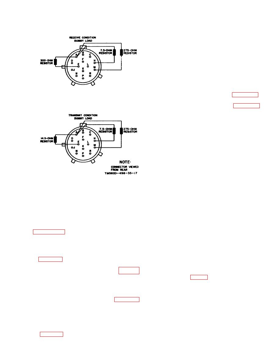
Figure 3-1. Fabrication of transmit and receive dummy load assemblies. |
|
||
| ||||||||||
|
|  TM 11-5820-498-35
NOTE
The PP-2953(*)/U is normally internally ad-
justed for 25.2 volts dc output (TM
11-6130-233-12). Throughout this manual, a
dc power source of 25.5 volts dc is indicated.
Accordingly, if the PP-2953(*)/U is used,
25.2 volts dc should be measured where 25.5
volts is mentioned.
(b) Connect the PP-2953(*)/U to the ac
power source.
NOTE
If the TF-523/U is required (para 3-3c),
connect it between the ac power source and
the PP-2953(*)/U as shown in figure 3-3.
Refer to TM 11-5950-212-15 for instructions
to modify the PP-2953(*)/U's CX-4524/U
for use with the PP-2953(*)/U. Set the TF-
5 2 3 / U POWER switch to OFF and the
VOLTS ADJUST control fully counterclock-
wise (O volt output) before making connec-
tions.
(c) Lay the AM-2060(*)/GRC on the
MT-1029/VRC and push it back until the connec-
t o r s are fully together. Fully tighten the
MT-1029/VRC mounting clamps to hold the
AM-2060(*)/GRC in place.
NOTE
A receiver-transmitter can be mounted on the
Figure 3-1. Fabrication of transmit and receive dummy
AM-2060(*)/GRC and connected to it using
load assemblies.
the CX-4655/GRC.
minal of the dc power supply, and the blue-
(d) To turn on the equipment, set the
green leads are connected to the minus (-)
PP-2953(*)/U AC and DC power switches to ON;
terminal of the dc power supply.
the NORM indicator lamp should light. Set the
a. Using Mounting MT1029/VRC. Before using
PWR switch on the AM-2060(*)/GRC to ON
the MT-1029/VRC, check to see that the link in
when desired. If the TF-523/U is used, set its
the connecting box is positioned as shown in
POWER switch to ON and adjust the control until
for
directing
power
to
the
the voltmeter indicates 115 volts. The amount of
AM-2060(*)/GRC.
current drawn by the equipment will be shown on
NOTE
the ammeter.
If the link were positioned between pivot and
(2) Dc power source other than PP-2953
terminal E22 as shown in dashed lines in
(*)/U.
(a) If a dc power source other than the
AM-2060(*)/GRC when the PWR switch is
PP2953(*)/U is used ((1) above), connect the
set to ON. (See MT-1029/VRC in figure 4-
MT1029/VRC to the dc power source; use the
4.).
CX-4720/VRC (fig. 3-3). (See caution 2 above.)
(b) Lay the AM-2060(*)/GRC on the
(1) Using PP-2953 (*)/U.
M T - 1 0 2 9 / V R C and push it back until the
(a) If the PP-2953(*)/U is used, connect
AM2060(*)/GRC and MT-1029/VRC connectors
C X - 4 7 2 1 / V R C between the PP2953(*)/U
are
together.
firmly
Fully
tighten the
d the MT1029/VRC as shown in figure 3-3.
MT-1029/VRC mounting clamps to hold the
NOTE
AM2060(*)/GRC in place.
Since the PP-2953(*)/U can supply up to ap-
NOTE
proximately 10 amperes, two OA-3633(*)/
A receiver-transmitter can be mounted on the
GRC may be tested at the same time, in-
AM2060(*)/GRC and connected to it using
cluding receiver-transmitted, as shown in
the CX-4655/GRC.
3-3
|
|
Privacy Statement - Press Release - Copyright Information. - Contact Us |
