 |
|||
|
|
|||
|
Page Title:
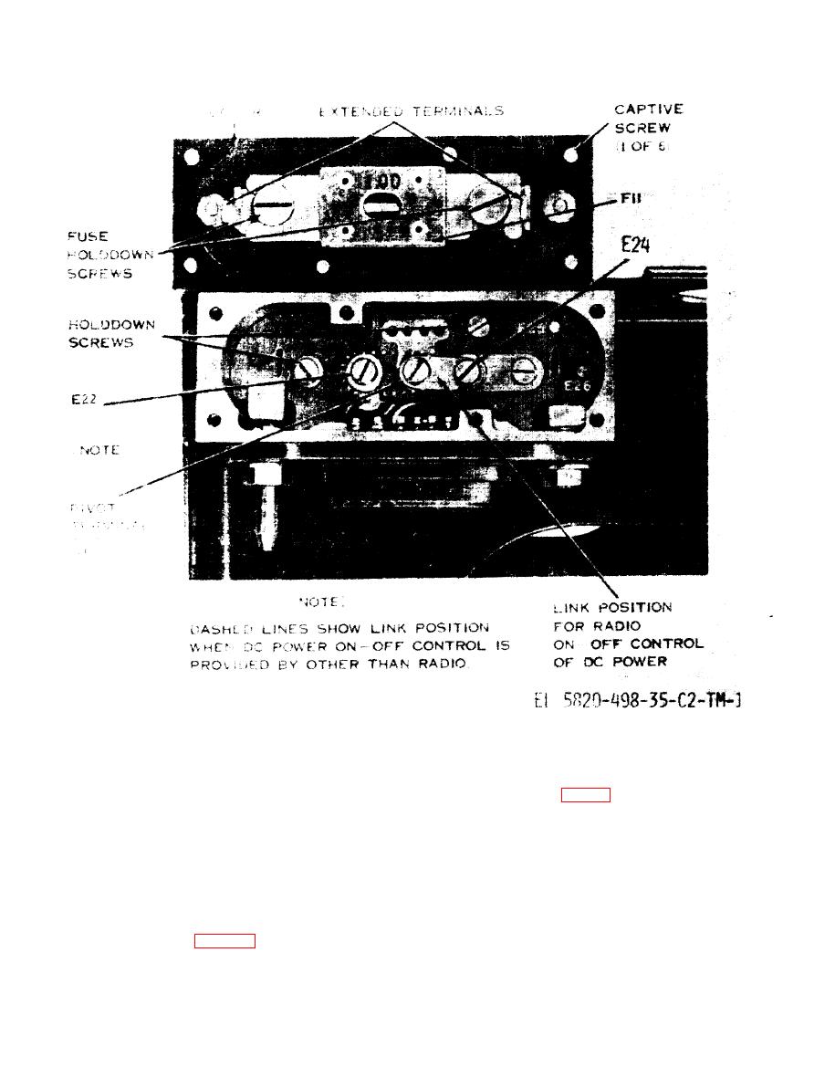
Figure 3-2. View of MT-1029/VRC connector box with cover removed showing position of link. |
|
||
| ||||||||||
|
|  TM 11-5820-498-35
Figure 3-2. View of MT-1029/VRC connector box with cover removed showing position of link.
(c) Turn on and adjust the output of the dc power
the rear of the box, and the elliptical receptacle on
supply to 25.5 volts. Set the PWR switch on the AM-
the front of the box (fig. 3-4).
(3) Interconnect the following pins of the recep-
2060(*)/GRC to ON when desired.
b. Using Fabricated Power Distribution Box (fig. 3-
tacles; use insulated # 14 AWG wire:
4). When the MT-1029/VRC is not available, dc power
(a) Interconnect pins A(+) and B(-) of the oval
may be applied to the AM-2060(*)/GRC through a
receptacles.
power distribution box, fabricated and used as
(b) Interconnect pins A and B of one of the
follows:
oval receptacles with pins A and J of the elliptical
(1) Obtain the MT-1029/VRC oval power recep-
receptacle.
tacles J21 (male) and J23 (female), and the elliptical
(4) To make the power connections, proceed as
power receptacle J24 (para 3-3b).
follows:
(2) Fabricate a small, sturdy, metal box large
(a) Turn off the dc power supply being used
enough to mount the two oval receptacles and the
and connect the CX-4720/VRC to it; see caution 2
elliptical receptacle. Mount the oval receptacles on
above. Connect the other end of the
34 Change 2
|
|
Privacy Statement - Press Release - Copyright Information. - Contact Us |
